Tuesday Feb. 28, 2017

You probably didn't enroll in this class thinking that you'd be spending so much time reviewing principles of electricity & magnetism, learning about small ions, conductivity, and that sort of thing.   No, you probably thought (hoped?) the class would be mostly about lightning.  And much of the rest of the class will be, beginning with this lecture.  We'll start with a fairly qualitative look at lightning phenomenology.  We'll concentrate primarily on cloud-to-ground lightning. 

Broadly speaking there are two types of lightning

Intracloud (IC) lightning remains in the cloud and is the most common type of discharge.  Approximately 1/3 of lightning discharges travel between charge in the cloud and the ground.  We'll use the term cloud-to-ground even though some relatively rare lightning discharges start at the ground and travel upward toward the cloud.

Most CG discharges, "negative cloud-to-ground", carry negative charge to ground.


Most CG discharges begin with an in-cloud, preliminary breakdown, process.  One of the lower positive charge centers LPCC) is probably involved in the initiation of most negative CG discharges.  One of the interesting and as yet unsolved problems is how localized fields in the cloud become high enough to breakdown air (30,000 volts/cm is needed at sea level altitude, 3 x 10⁶ V/m).  Once breakdown is initiated fields in a larger volume must be high enough for a discharge to continue to propagate.

Pay attention to the branching in this and the figures that follow.  The branching tells you the direction of the initial leader process in the discharge (we'll learn more about the leader processes shortly).  The photograph above is from a Wikipedia article on lightning.


We've mentioned before that some CG discharges begin higher in the cloud and carry positive charge to the ground.  They too are initiated by a positively-charged, downward moving leader process.


Positive CG discharges are more common
(i)  in severe thunderstorms where vertical wind shear is present (faster winds at upper levels than lower altitudes).  Normally the positive charge center is above the main negative charge and discharge between the two remain in the cloud.  Wind shear can cause the cloud to tilt and move some of the positive charge away from a position directly above the main negative charge center.  Discharges can then travel from the cloud to the ground.


(ii)  in storms at high latitudes where the positive charge center is closer to the ground.

(iii)  in winter storms.  The positive charge center is closer to the ground.  Vertical wind shear may also be present

(iv)  at the ends of summer air mass thunderstorms like we have in Arizona.  The cloud may tilt or the anvil and positive charge can be blown away from the main body of the cloud. 

(v)  in storms with an inverted charge distribution as discussed in the lecture on cloud electrification.

Positive CG discharges usually just have a single return stroke though the return stroke peak current is often very large 100,000 A or more (negative CG discharge peak return stroke currents are usually 30,000 A or less).  The positively charged leader than initiates a positive CG discharge shows little or no stepping (we'll discuss the negatively charged "stepped leader" that initiates negative CG discharges shortly). 


Tall buildings and towers are struck relatively often by lightning.  Often these are discharges initiated or triggered by the structure itself.


Note the direction of the channel branching.  These discharges begin at the ground with the development of an upward moving, positively charged, leader (very rarely the discharge can begin with an upward negatively charged leader).  The upward leader is followed by downward negatively charged leaders and upward return strokes, which is, as we shall see, the normal sequence of events in negative CG lightning.  The photo above shows upward lightning initiated by the Suchá Hora transmitter tower as seen from Banksa Bystrica, Slovakia, and is from a Wikipedia article on lightning.

We saw in an earlier lecture that because they enhance the local electric field, launch vehicles sometimes trigger and are struck by lightning.  Researchers are now able to trigger lightning discharges using small rockets.  A spool of wire attached to the base of the rocket unwinds as the rockets travels upward.  If conditions are right, an upward leader is initiated when the rocket reaches an altitude of 50 to 100 m or so.  Direct measurements of lightning return stroke currents and close (10 meters or less) E and B field measurements can be made.


Now we'll look in more detail at the sequence of processes that occur during negative cloud-to-ground discharges.


The discharge begins with some kind of in-cloud preliminary discharge involving the main negative charge center and one of the lower positive charge centers.  Then a downward moving, negatively-charged discharge begins moving toward the ground.  This is called the stepped leader discharge because the channnel advances in steps of about 50 m length every 50 microseconds or so.  The 50 m long channel extensions occur rapidly (less than 1 microsecond duration) and produce a bright flash of light.  Think of dropping a strobe light from aircraft altitude and watching it flash on and off as it falls to the ground.


It takes a few 10s of milliseconds for the step leader to travel a few kilometers from the cloud to near the ground.  This corresponds to an average speed of 1 to 2 x 10⁵ m/sec (traveling from 6 km altitude in the cloud to the ground in 30 msec would result in a speed of 2 x 10⁵ m/sec.  Negative charge is carried from the main negative charge center and distritbuted along the length of the leader channel.   Currents flowing in the leader channel range from 100s to about 1000 Amps.

The individual step, or extension of the leader channel, occurs in less than 1 microsecond.  The velocity of the step is 5 x 10⁷ m/s or faster (50 m in 1 μs is 5 x
107 m/s) and the step current is 1 kA or more.

Images of stepped leader have been captured using streaking cameras (cameras with moving film) and, more recently, on video cameras with high framing rates.  The next figure tries to illustrate how a descending leader might appear on film.

Because the film is moving (to the left), each of the images is displaced slightly (to the right) on the film.  Extensions of the channel (the step) produce the most light (highlighted in yellow above) but the remainder of the channel is usually weakly illuminated.  The descending channel breaks up into branches and then the ends of the separate branches begin to independently step and move toward the ground.

Here's a short description of the Boys Camera that was used originally to photograph the sequences of processes in cloud-to-ground lightning with fast time resolution.  This is from Martin A. Uman's book Lightning (reissued by Dover Publications, New York, 1984) which has an excellent survey of early photographic studies of lightning.  You'll find some additional discussion of streaking photography in "Lightning Return Stroke Velocities in the Thunderstorm Research International Program (TRIP)"  by V.P. Idone and R.E. Orville.


Here are a couple images of actual streak camera photographs of a stepped leader (left) and a dart leader (right).  They were given to me by Dr. Vince Idone a professor at the State University of New York at Albany. 

You can clearly distinguish the separate steps in the upper half of the left image.  We haven't really discussed dart leaders yet but they travel continuously from the cloud to ground (without stepping) and at a higher speed than stepped leaders.

You can see some additional examples of streak photographs of lightning leaders in
"Lightning Leader Characteristics in the Thunderstorm Research International Program (TRIP)", by R.E. Orville and V.P. Idone, in an article titled "Novel Observations of Lightning Discharges: Results of Research on Mount San Salvatore" by Karl Berger and in "Progressive Lightning" by B.F.J. Schonland and H. Collens (published in the Proceedings of the Royal Society of London and the first of a  series of reports on early lightning research conducted in South Africa).  

We won't cover the attempts that have been made to understand or simulate stepped leader channel development.  It would be very difficult to produce a stepped leader discharge in a laboratory because each step is 50 m long.  Here's my conception of what leads up to an extension of the stepped leader channel.


Basically the leader consists of a low resistance arc core that is surrounded by a space charge envelope.  High fields exceed breakdown strength at the bottom end of the propagating channel and discharge tendrils grow out into the air ahead of the leader.  Initially this is a high resistance "glow discharge".  As the discharge filaments increase in number and lengthen, more and more current flows from the bottom end of the arc core.  This must heat the channel enough that at some point, a portion of the glow discharge channel will change to a conducting arc.  It is this sudden change from glow to arc discharge that produces a brief pulse of current and light.  This is the step that effectively lengthens the leader channel. 

This seemed like a good point to have a look at a slow motion video of an actual stepped leader.  This is a video of a negative cloud to ground discharge with just a single return stroke.  A video camera that captures 7200 images per second was used (the video is then slowed down considerably during play back).  The video begins at about 18:25:53.123566 and ends about 130 ms later (the discharge had not ended at that point).  The downward moving stepped leader appears at the top left edge of the picture at about 53.137000 seconds and reaches the ground (initiating a return stroke) about 14 ms later (53.151 seconds).   The fact that the return stroke channel remains luminous means that a relatively low ampltitude continuing current is flowing.  This continuing current was still flowing when the video ended at about 18:25:53.254823.

And here is a site with high-speed videos of a negative stepped leader, a downward positive leader, and an upward positive leader.  I would suggest looking at just the first video at this point, we'll come back to the downward positive leader (that initiated a positive cloud-to-ground discharge) and the upward positive leader later in the lecture.

Multiple strikes to the ground are visible in the first video which lasts about 0.54 seconds (starts at about 17:53:43.063 and ends about 17:57:43.604).  Here's a rough time line showing the events (most of which we haven't yet mentioned or discussed) that I was able to see (with some practice you can click the play and pause buttons quickly enough to be able to step through the event millisecond by millisecond.

time on video
elapsed time (ms)
comments
17:57:43.062968

start of video
          43.066160
0
stepped leader appears top right of center
          43.075316
9
1st return stroke
          43.091270
25
branch visible in picture (from another stroke outside the frame?)
          43.119850
54
dart leader
          43.121652
56
2nd return stroke (more distant strike point)
          43.149816
84
3rd return stroke (at more distant strike point)
          43.171735
106
new stepped leader
          43.187551
121
4th return stroke (at original location)
          43.206002
140
dart leader
          43.206696
140
5th return stroke with continuing current at more distant location again
          43.522490

end of continuing current
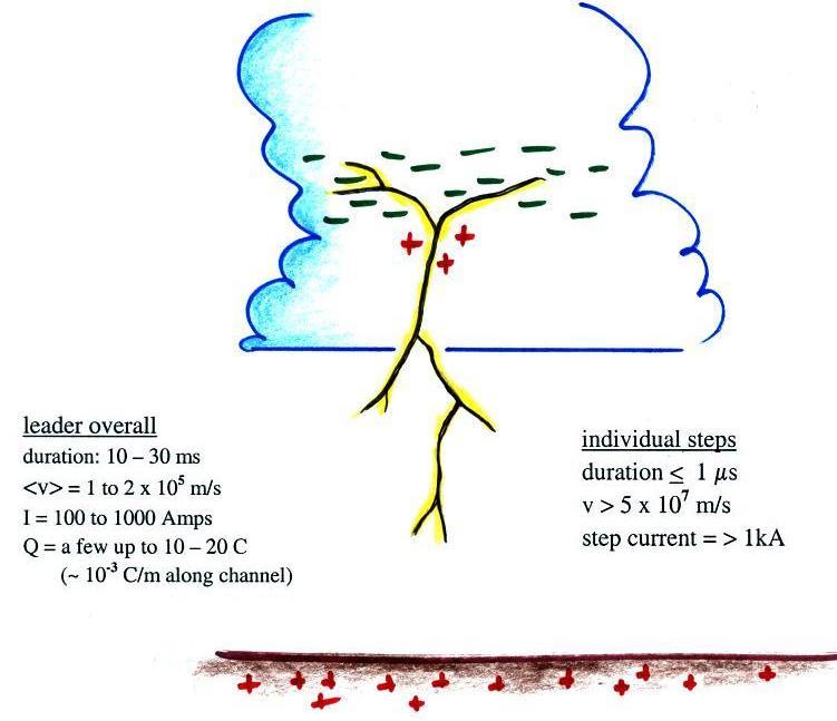


When the stepped leader approaches to within a few hundred meters of the ground, the electric field at the ground intensifies to the point that several positively charged, upward propagating discharges are initiated.  One of these will intercept the stepped leader and determine where the lightning will strike the ground.


The striking distance referred to in the figure is typically 10 to 20 m above flat ground and 20 to 100 m above taller objects.  This is a reasonably important parameter in the design of lightning protection design, a topic we will cover later in this class.

There are probably less than a dozen good photographs of upward connecting discharges.  One of the best was taken by Johnny Autery in Alabama (see M.A. Uman, "The Best Lightning Photo I've Ever Seen" Weatherwise, 44, 8-9, 1991).  The photograph is copyrighted but I've sketched it below and have pointed out some of the main features.

You can see the actual photograph on the photographers homepage (and in Uman's article referenced above).  There were at least 3 upward discharges initiated by the approach of the stepped leader (1, 2, and 3 in the sketch).  Streamer 1 connected to the bottom of the stepped leader.  It isn't clear where the exact junction point was, perhaps at the point where the channel takes a bend to the right.  The downward branching at Point 4 indicates that was part of the descending stepped leader.  A very faint upward discharge can be seen at Point 3.

Not long after the Spring 2013 edition of the class I learned about another image.  It was taken by Carey Walton and can be viewed here (click on the Galleries link at the top of the page and then on Lightning Gallery 1). 

And as luck would have it a new image was taken in July 2015 in southern New Mexico by Mike Olbinski, a Pheonix wedding photographer and storm chaser.  A closeup of one of two lightning channels striking the ground shows 12 branched upward connecting discharges (discharges that did not connect with the stepped leader as it neared the ground.  Olbinski et al. (2016) have published an analysis of the photograph.  We'll have a look at the photograph in class; you should also have a look at some of the storm photographs on his homepage (http://www.mikeolbinski.com/)

Many of the remaining examples can be seen on pps 141 & 142 in Rakov and Uman's book "Lightning Physics and Effects."  As chance would have it this portion of the book can be viewed online here (you may have to scroll up or down to find pps 141 & 142).  There are also some good examples in this gallery of images.


Junction between the upward connecting discharge and the stepped leader electrically connects charge in the cloud to ground and a large amplititude pulse of current travels rapidly back up the channel.  This is the first return stroke discharge.


The tip of the return stroke propagates up the channel at a speed of about 1 x 10⁸ m/s (1/3 the speed of light) taking about 100 microseconds to travel from the ground to the cloud.  The 1st return stroke has a peak current of typically 30 kA.  Current rises to peak value in a few microseconds and the peak dI/dt is about 100 kA/us.  The return stroke heats the air to a peak temperature of about 30,000 K (5 times hotter than the surface of the sun).  The overpressure creates a shock wave that quickly decays into a sound wave that we hear as thunder. 

I often use the following analogy to help understand the return stroke process.

Now imagine what you would see if the hand at the bottom of the tube is removed.


And now back to the stepped leader channel and all the negative space charge surrounding it.

The intense action is really at the tip of the upward propagating return stroke.  The large potential difference (cloud potential in close proximity to ground potential) ionizes the air, creates large currents, heats the air, and produces a bright flash of light.  The potential difference wave can propagate rapidly up the channel (and out into the branches).  Once the potential wave passes a point on the channel the space charge envelope collapses and electrons into and then down the conducting channel to ground.


Some cloud-to-ground discharges end at that point.  I.e. they consist of (i) a downward, negatively charged, stepped leader, (ii) a relatively short upward connecting discharge, and (iii) an upward return stroke that travels from the ground to the cloud at about 1/3 the speed of light. 

Most cloud-to-ground discharges however contain multiple strokes.  A schematic illustration of a 4 stroke cloud-to-ground is shown below.


The discharge begins at left in the figure with a branched stepped leader that is followed by a 1st return stroke.  The stepped leader takes a few 10s of milliseconds to travel from the main negative charge center in the cloud to the ground. The ensuing 1st return stroke travels back up the channel to the cloud is about 100 microseconds.

Then, with a few slight differences, the process repeats itself.  Additional discharges occur typically at intervals of 50 to 100 ms and are usually preceded by a dart leader that travels, without stepping or branching, down the existing main channel.  A short upward connecting discharge is initiated when the dart leader gets close to the ground and then a subsequent return stroke travels back up the channel to the cloud.  We'll look at the dart leader and subsequent return stroke processes in a little more detail shortly.


The 3rd return stroke in the illustration above is following by a continuing current.  This is a low amplitude (100s of Amperes) current that continues to flow for 10s of milliseconds or more typically, which keeps the return stroke channel luminous.  Short duration rebrightening of the channel sometimes occurs during the continuing current, these are called M-components.  These are the features visible in the slow motion video of a single cloud-to-ground discharge showed earlier (here's a link to the video if you'd like to watch it again).

The bright flashes of light produced by multiple return strokes produces the flickering that you sometimes sees when observing cloud to ground lightning.  If you deliberately move a camera back and forth while photographing lightning the separate strokes will be displaced on the image.  The technique is described in an article "Panning for Lightning," by John Hendry Jr. that was published in Weatherwise Magazine (vol. 45, No. 6, pps 18-19, Dec. 1992/Jan 1993 issue).   Here is an example (source: http://www.odec.ca/projects/2005/schu5s0/public_html/lightning.html ).


This appears to have been a 4 stroke flash.  The rightmost channel in the photograph is branched so that is the first return stroke.  Separation of the return strokes channels like this can sometimes be caused by wind.  That is referred to as "ribbon lightning."


Next some more information about dart leaders and subsequent return strokes.


Sometimes the dart leader will depart from the existing channel and form a new channel to ground.  Because it is traveling through air that hasn't been ionized, the lower portion of the dart leader would turn into a stepped leader.

Occasionally there is sufficient time between strokes that the existing channel can begin to cool and become less conductive.  Under these conditions the dart leader becomes a dart-stepped leader.  The steps of a dart-stepped leader are shorter and occur more frequently than a stepped leader.


Subsequent return stroke characteristics are summarized in the table below

peak current
10 kA
peak current derivative
100 kA/μs
velocity
1 x 10⁸ m/s

A short video was shown at this point (it was produced by Ken Cummins and Shipherd Reed for a display at the Flandrau Science Center on campus).  It reviews and also has some nice video examples of the phenomena we have been covering.  I can't include a link in these online notes because the video contains some copyright protected material.


Statistics on the number of strokes per flash are shown in the following two histograms (source:
Lightning: Physics and Effects, V.A. Rakov, M.A. Uman, Cambridge Univ. Press, Cambridge, 2003).

A mean of 4.6 strokes per flash was observed in the 76 flashes in Fig. (a) from Florida. Only 17% of the flashes contained just one return stroke.  In Fig. (b) the mean was 6.4 strokes per flash in 83 flashes recorded in New Mexico; 13% of the events were single stroke flashes.

Many lightning parameters or characteristics are log-normally distributed.  This appears to be the case with the interval time between return strokes distribution in the next figure (also from the Lightning: Physics and Effects source mentioned above)

Shown are 516 interstroke intervals from 132 flashes recorded in Florida and New Mexico.  The shaded data are intervals preceding strokes that initiated long continuing currents.

Up to now we really haven't considered the possibility that dart leaders and subsequent return strokes might depart from the channel created by the stepped leader and 1st return strokes.  That does often turn out to be the case.  This means that the separate strokes in a flash do not always strike the same point on the ground.  The illustration and statistics below come from
"Statistics and characteristics of cloud-to-ground lightning with multiple ground contacts," W.C. Valine and E.P. Krider


In a new channel flash one (or more) of the subsequent strokes follows a different channel to ground.  A connection between the new and original channel is assumed to occur somewhere in the cloud.  In an altered channel flash the new portion of the channel can be seen departing from the original channel somewhere between the cloud base and ground.


386 flashes in 7 Arizona air mass thunderstorms were photographed (video photography) for this study.  135 flashes (35%) contained just a single stroke, 251 flashes (65%) were multistroke flashes.  Note that on average a flash has 1.45 strike points.  We will make use of this number later in the course when we discuss lightning location techniques and estimates of lightning flash densities, an important parameter in lightning protection and lightning risk assessment.


A distribution of the number of strokes per flash observed in the Arizona study.  The mean, 2.8 strokes/flash, is a little lower than the mean values mentioned earlier for the Florida and New Mexico data sets.


Next we look at how a multi-stroke cloud-to-ground discharge might appear on slow and fast electric field antenna records.  We might have done this earlier in the semester but now you should have a better understanding of the various processes involved.


The sequence of events shown on the sketch of a high-speed photograph record of a discharge at the top of the figure should be familiar by now. 

Point 1a on the slow E field record shows the field change produced by the stepped leader (the E field at the ground points upward toward the negative charge being lowered by the leader (the negative going E field change in the figure means the atmospheric electricity convention for E field polarity is being used here).   The dart leader field changes are shown at Points 1b.  They are smaller in amplitude (the dart leader doesn't lower as much charge as the stepped leader) and have shorter durations. 

The abrupt return stroke changes are shown at Points 2 on the slow E and the fast E records.  Note one the slow E field record that the leader and return stroke field changes are of opposite polarity.  The return stroke removes negative charge from the leader channel, charge that came from the main negative charge center in the thundercloud.  The overall effect is the same as if a quantity of positive charge had been added to the cloud and used to neutralize the negative charge.

Points K on the fast E field record are "K changes."  During the interval between return strokes, in-cloud leader processes seek out additional pockets of charge in the cloud.  Occasionally, when the leader finds a concentration of charge, a rapid recoil streamer travels back along the in-cloud leader channel (in some ways like a return stroke propagates back along the leader in a cloud-to-ground strike).  The K changes are probably produced by these recoil streamers.

The preliminary discharge process that initiates cloud-to-ground discharges is not well understood.  Sequences of bipolar waveforms like shown at Point 3 though are thought to be associated with the preliminary breakdown process.

Point 4 shows E field pulses thought to be produced by the last few steps of the stepped leader as it approaches the ground. 

The fast E field waveforms produced by 1st and subsequent strokes are distinctly different.  The 1st return stroke field variations following the peak are considerably noisier than is observed with subsequent strokes.  Some of the "noise" on the 1st return stroke E field record is probably produced by branches.  Some of the structure on both the 1st and subsequent stroke waveforms is probably due to the tortuous shape of the channel.

Some of the modern lightning detection and location instrumentation is able to distinguish between return stroke waveforms and waveforms produced by leaders or discharges that occur during the preliminary breakdown activity.

The next figure is essentially the same except that some continuing current has been added following the second stroke.

A continuing current is a low level current (10s to 100s of Amperes) that continues to flow after a return stroke for 10s to a few 100s of milliseconds.  The continuing current can transport significant quantities of charge to the ground (100 ms x 250 Amps = 25 C ).  Continuing currents can burn through metal sheets or metal skins on aircraft bodies.  A CG lightning discharge with continuing current is sometimes referred to as "hot lightning" because these discharges are more likely to cause a forest fire than a discharge without continuing current.  A field change associated with the continuing current is visible on the slow E field record.  M components are a re-brightening of the lightning channel that occurs during a continuing current.  The K changes seen on the fast E field trace may be associated with the M components.


Now we'll go back and look at the high speed video of a positive cloud-to-ground flash ( click on this link and have a look at the 2nd of the 3 videos).

At about 01:34:16.211 seconds you'll see a bright, diffuse flash of light occurring inside the cloud. 
Shortly thereafter, starting at about 16.219 seconds you'll begin to see the tips of leader channels emerging from the base of the cloud. 

I think you will agree that the overall appearance of this downward positively charged leader is different from the negative stepped leader discharges we looked at early.  Here we see many short segments of channels flashing on and off at different locations below the cloud base.   Often you will just see flashing from short but complete channel segments that don't seem to be connected to the rest of the discharge.

Some sketches will help to explain what I think is happening. 


The spatial structure of the developing positive leader is similar to that of a stepped leader.  I.e. an initial single channel breaks into branches that themselves split into more branches as the discharge moves toward the ground.  The channels may develop more continuously without the stepping that we see in a stepped leader though.  Much of this structure is too faint to be visible or to be photographed, however.

The illumination of short, seemingly unconnected, segments of channel that we see in the video occurs when one of the leader tips encounters a volume of negative charge. 


Charge travels back up and illuminates a segment of the leader channel.  In many ways this is like the return stroke that forms when a stepped leader reaches the ground.


These recoil streamers occur intermittently and randomly while the leader is moving downward.  These brief recoil streamers are what we are mostly seeing on the video.


This is the same picture with all but the bright, recoil streamers parts of the channel shown.  Only three are shown here, there may well be 100s of these that occur during the time it takes a positive leader to travel down to the ground.

Here I've superimposed the three recoil streamers together on one image.  Only three are shown here, there may well be 100s of these that occur during the time it takes a positive leader to travel down to the ground.

At about 16.327 seconds in the video as the leader structure nears the ground you can see a leader move smoothly the rest of the way to the ground where it initiates a very bright return stroke at about 16.332 seconds.  Continuing current flows in the return stroke channel for most of the rest of the video.

Now have a look at the 3rd fast time resolved video (here's the link).  This shows an upward propagating positive leader that develops off the top of a communications tower in Rapid City, South Dakota.   A small portion of the upward channel structure remains visible during the entire video.  But again you see short segments of what seem to be unconnected segments of channel flashing on an off.  These are recoil streamers again that occur when the an upward positively charged leader tip encounters some negative charge.  Clearly much of the structure that formed during the discharge remained invisible throughout the discharge.  We are able to get some idea of its extent and complexity because portions of it are illuminated momentarily by the recoil streamers. 

The figure below, from an event where upward streamers were initiated simultaneously from 4 communications towers, gives you some appreciation for what you can see (or photograph with an ordinary camera) and what you don't always see, what really is happening (and being photographed by the high speed video camera).


Tracing of a still photograph (20 second exposure) of positive upward streamers that developed off the tops of 4 transmission towers in Rapid City, South Dakota.  See
T.A. Warner, "Observations of simultaneous upward lightning leaders from multiple tall structures," Atmos. Res., 117, 45-54, 2012.

Tracing of a superposition (time integration) of images captured with a high-speed video camera (7207 images/sec).  The high speed camera has greater light sensitivity than the still camera.

Finally it is worth asking (and trying to explain) what initiated the upward streamers.  In the majority of cases they follow an earlier, nearby positive cloud-to-ground flash.


Positive cloud-to-ground discharges often have long during continuing currents that might remove 100 C of charge from the thundercloud.  Horizontal negatively charged leaders develop and move horizontally outward away from the positive CG discharge.  They are seeking positive charge to supply and sustain the continuing current.  When they find and remove positive charge, negative charge is left behind.  The sudden appearance of negative charge overhead increases the electric field at the ground and initiates the upward streams.


References:

R.E. Orville and V.P. Idone, "Lightning Leader Characteristics in the Thunderstorm Research International Program (TRIP)," J. Geophys. Res., 87, 11177-11192, 1982.

K. Berger, "Novel Observations on Lightning Discharges: Results of research on Mount San Salvatore," J. Franklin Inst., 283, 478-525, 1967.

B.F.J. Schonland and H. Collens, "Progressive Lightning," Proc. Roy Soc. London, Series A, Vol. 143, No. 850, 654-674, 1934.

M. Olbinski, K.L. Cummins, E. P. Krider, and R.L. Holle, "Photo of Cloud-to-Ground Lightning Showing Multiple Upward Leaders," 24th Intl. Lightning Detection Conf., San Diego, 2016.

W.C. Valine and E.P. Krider, "Statistics and characteristics of cloud-to-ground lightning with multiple ground contacts," J. Geophys. Res., 107, doi:10.1029/2001JD001360, 2002.

T.A. Warner, "Observations of simultaneous upward lightning leaders from multiple tall structures," Atmos. Res., 117, 45-54, 2012.