First I thought it might be interesting to describe some recent experiments conducted at the International Center for Lightning Research and Testing. The experiments involved injecting return stroke currents from triggered lightning directly into the lightning protection system of a home in order to see how well the system performed. In a initial experiment (an experiment conducted in 1997 and discussed by Rakov et al. 2002) peak currents at some points in the home's wiring exceeded 80% of the injected current's peak value which was quite a bit higher than was expected. Here we will summarize a followup experiment conducted in 2004 (DeCarlo et al., 2008)).
 |
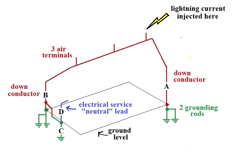 |
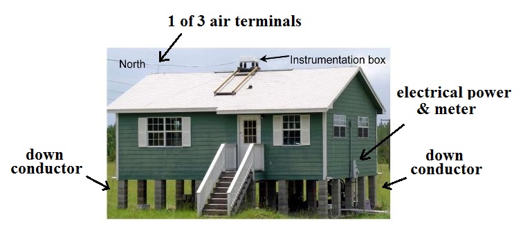
| A photograph of "test house" is shown above at left (from DeCarlo (2008)). The dimensions of the house were about 10 m x 7 m x 6.5 m. | Schematic diagram of the lightning protection system. Each of the down conductors was connected to two grounding rods at diagonal corners of the house. The neutral lead of the electrical power service was connected to an additional grounding rod which was connected to one of the down connectors. Currents were measured at points A, B, C, and D and inside the house. |
A more complete wiring diagram is shown below. Lightning currents from triggered lightning were injected directly into the lightning protection system (into one of the air terminals on the top of the house).
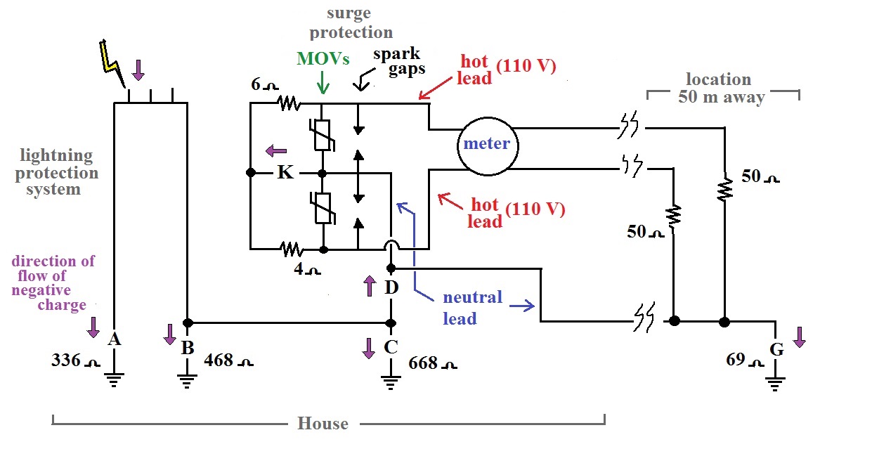
The lightning protection system is shown in the left part of the figure. The LPS consisted of 3 air terminals all connected together by a wire that ran the length of the roof of the house, two down conductors at diagonally opposite corners of the house. Each of the down conductors was connected to two grounding rods (about 6 m apart) that were connected together. The neutral lead ground was connected to one of the down conductor ground with a buried cable. Grounding resistances of all the grounds are shown above.
Surge protection (MOVs and spark gaps) was connected between the two phase conductors and the neutral. There wasn't any interior wiring or appliances in the home, instead a simulated load consisting of two resistors connecting the phase conductors to the neutral was used.
During a strike, currents were measured at points A, B, C, D, K, and G. The purple arrows show the direction of flow of negative charge (current would be in the opposite direction).
 |
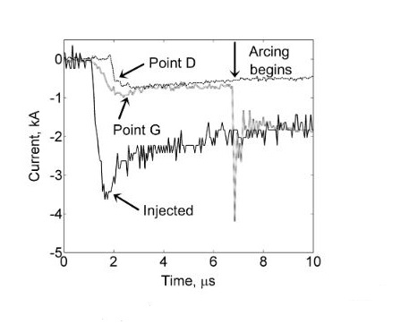 |
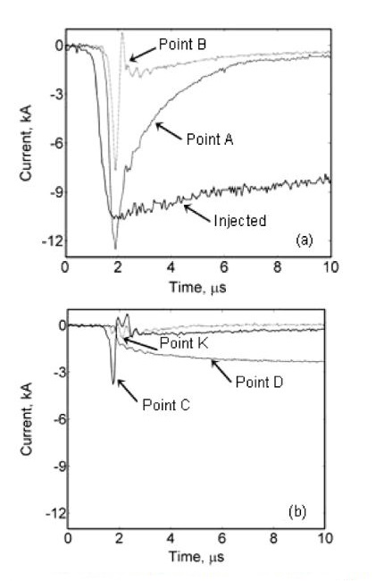
The left figure above shows
currents measured during the 3rd stroke of a 9
stroke flash.
The current measured at point A is the largest probably because it was closest to the current injection. Actually the peak current measured at point A is larger than the peak value of the injected current. This could be because there was coupling into a loop formed by the LPS (the roof wire, the 2 down conductors, and the ground form a large loop) and also because of coupling into the measuring system which might not have been shielded properly.
The current waveforms measured at points A, B, and C are narrower than the injected current waveform. It appears that mainly the high frequencies in the injected current waveform travel to the local ground, the lower frequencies travel through point D and into the house wiring (note that the current flowing through pt. D and into the house wiring, reaches a peak value of just under 3 kA). The grounding rods act more like a capacitive impedance to ground than a resistive impedance.
The waveforms at points D and G, shown in the right figure above are from stroke 7 in the flash (stroke 7 had the lowest injected peak current value) . The two waveforms are very similar, indicating that the current flowing through point D eventually flows to ground through point G at the location 50 m from the house. The arcing shown on the figure was current from a different experiment sparking across to the grounding rod at point G.
Currents measured at point D (i.e. currents flowing into the house wiring) ranged from about 1 to about 3 kA for the 9 stroke flash. Overall currents measured at pt. D ranged from 16% to 28% of the peak value of the injected current. This was considerably less than was observed in the earlier (1997) experiment and more in line with expectations.
I was surprised to learn that currents of this amplitude could potentially enter a home on the wiring in the event of a direct strike. And this is a house with a LPS, which would seem like a best-case scenario. However, there is no mention of a circuit breaker or fuses at the point where the electrical service entered the test house. Presumably if lightning were to strike the LPS of a real house, the fuses and/or circuit breaker would prevent currents of this intensity from flowing into a house.
One of the first protection considerations is the concept of topological shielding. This consists of nested enclosures that might each offer some degree of shielding. Incoming transients are reduced at the entrance to each successive enclosure. The idea is shown on the figure reproduced below (source: "Applications of Advances in Lightning Research to Lightning Protection," M.A. Uman, Ch. 5 in The Earth's Electrical Environment, National Academy Press, 1986. available online)
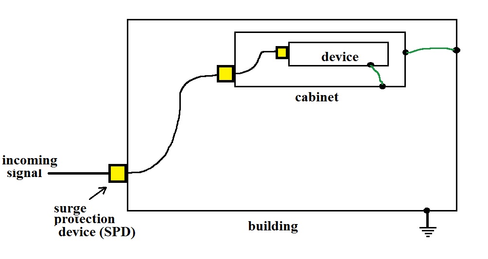
In a home the
first line of defense could be surge protection
outside the home at the circuit breaker box where
electrical service arrives or where the cable TV
or phone line signals connect to a house.
Once in the home plugging sensitive electronic
equipment into a surge protector would offer
additional protection against transients still on
the power line. Electronics equipment itself
will often have surge protection installed on
circuit boards inside a device.
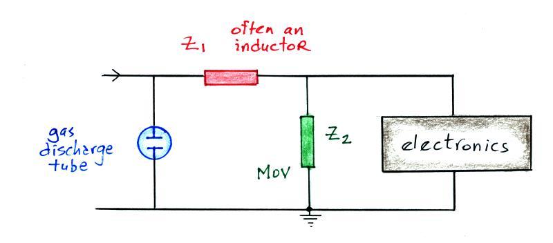
What might the transient protection look like. In the most general terms it will probably consist of a blocking impedance followed by a shunt impedance.
What might the transient protection look like. In the most general terms it will probably consist of a blocking impedance followed by a shunt impedance.
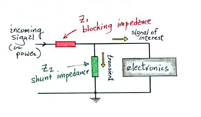
The blocking
impedance should present a high impedance to the
transient signal to prevent it from reaching the
electronics. The shunt has a low impedance
and will divert the transient signal to ground.
For the signal of interest, Z1 should appear as a low impedance. You might use an inductor if the incoming signal is low frequency (60 Hz power for example) and you want to block high frequency transients. If the incoming signal is high frequency, a capacitor would block low frequency transients.
The shunt resistance should appear as a high impedance for the signal of interest, a capacitor if the incoming signal is low frequency.
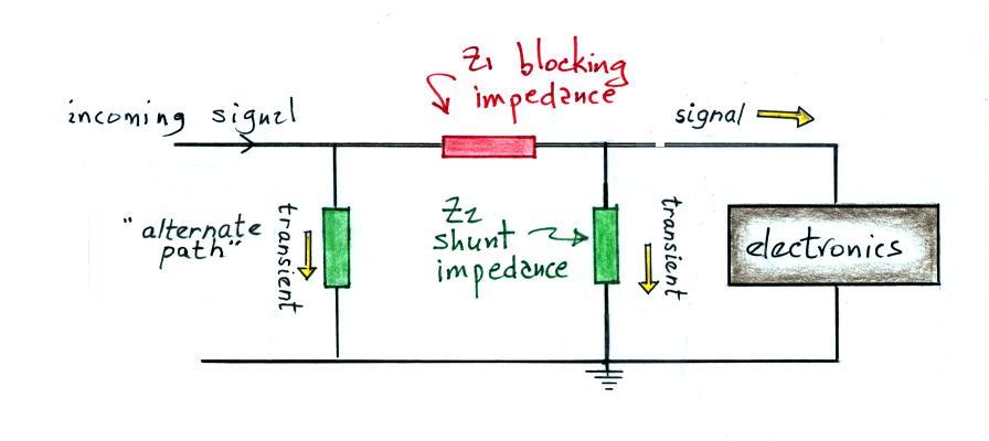
I have been taught that it is a good idea to provide an alternate path to ground for an incoming signal that encounters a blocking impedance (though the blocking impedance may also cause the transient signal to be reflected rather than diverted). I.e. something like the following:
For the signal of interest, Z1 should appear as a low impedance. You might use an inductor if the incoming signal is low frequency (60 Hz power for example) and you want to block high frequency transients. If the incoming signal is high frequency, a capacitor would block low frequency transients.
The shunt resistance should appear as a high impedance for the signal of interest, a capacitor if the incoming signal is low frequency.
I have been taught that it is a good idea to provide an alternate path to ground for an incoming signal that encounters a blocking impedance (though the blocking impedance may also cause the transient signal to be reflected rather than diverted). I.e. something like the following:
The first component is often a gas discharge tube.
A gas discharge
tube or "spark gap" is an example of a "crowbar"
device. It creates a short circuit (like
putting
a crowbar across the signal leads) once
it exceeds a certain voltage threshold. The
figure below (from Uman's lightning protection
book) shows the operating characteristics of a
typical gas discharge tube.
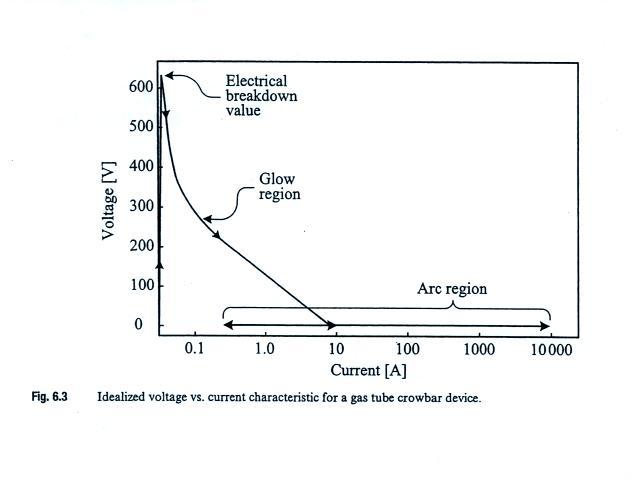
The spark gap
depicted here quickly becomes conducting once a
voltage threshold of about 600 volts is
crossed. Spark gaps can carry large
currents and are bipolar. They turn on
relatively slowly however (~1 μs). Note
that once created the arc discharge can be
maintained even at low current levels. A
device like this is sometimes difficult to "turn
off."
The role of the gas discharge tube is not to carry or divert all of the transient signal to ground. Rather the transient signal is reflected back in the direction it came from. A short discussion of reflection at the end of a short circuited line and a line with infinite impedance (open circuit) has been added to the end of today's notes.
MOV in the figure stands for metal oxide varistor. A varistor is a voltage-controlled resistor. The operating characteristics are shown below (again from Uman's book). Varistors are clamping devices which means they hold or limit the voltage to a particular value.
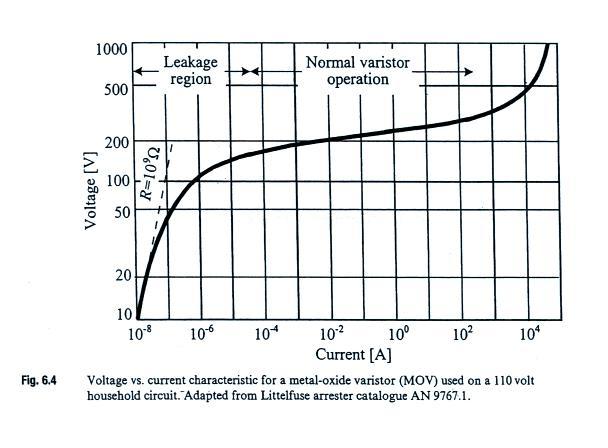
In the figure above, the varistor becomes active when the voltage across it reaches perhaps 180 volts (prior to that it has a large impedance). The voltage is then held at about that value until the current through the varistor reaches perhaps 100 A (currents higher than that would presumably destroy the device). A 200 v clamping voltage would be appropriate for a 110 volt AC power line. MOVs turn on very quickly (nanoseconds) and are bipolar. They do however have a relatively high capacitance and are not able to divert overvoltages for a sustained period of time.
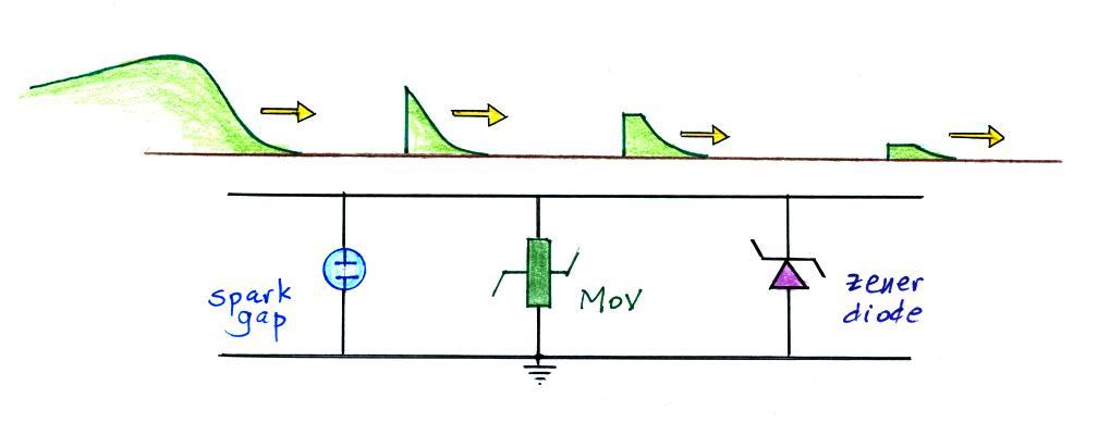
The MOV could be followed by another shunt impedance such as a zener diode which would clamp the incoming signal to an even lower voltage. This is sketched below. Each device adds some additional attenuation of the transient signal.
The role of the gas discharge tube is not to carry or divert all of the transient signal to ground. Rather the transient signal is reflected back in the direction it came from. A short discussion of reflection at the end of a short circuited line and a line with infinite impedance (open circuit) has been added to the end of today's notes.
MOV in the figure stands for metal oxide varistor. A varistor is a voltage-controlled resistor. The operating characteristics are shown below (again from Uman's book). Varistors are clamping devices which means they hold or limit the voltage to a particular value.
In the figure above, the varistor becomes active when the voltage across it reaches perhaps 180 volts (prior to that it has a large impedance). The voltage is then held at about that value until the current through the varistor reaches perhaps 100 A (currents higher than that would presumably destroy the device). A 200 v clamping voltage would be appropriate for a 110 volt AC power line. MOVs turn on very quickly (nanoseconds) and are bipolar. They do however have a relatively high capacitance and are not able to divert overvoltages for a sustained period of time.
The MOV could be followed by another shunt impedance such as a zener diode which would clamp the incoming signal to an even lower voltage. This is sketched below. Each device adds some additional attenuation of the transient signal.
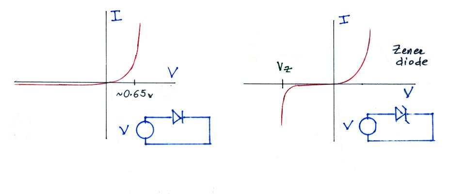
The figure below
contrasts the operation of an ordinary
diode and a zener diode.
Despite a large increases in total population, the number of people killed by lightning every year in the United States has dropped by an order of magnitude in the last century or so (from more than 400 per year in the early 1900s to about 30 per year at the present time). The same is true in many other developed countries in the world. The most recent estimates that I could find are summarized below (adapted from Holle (2015)).
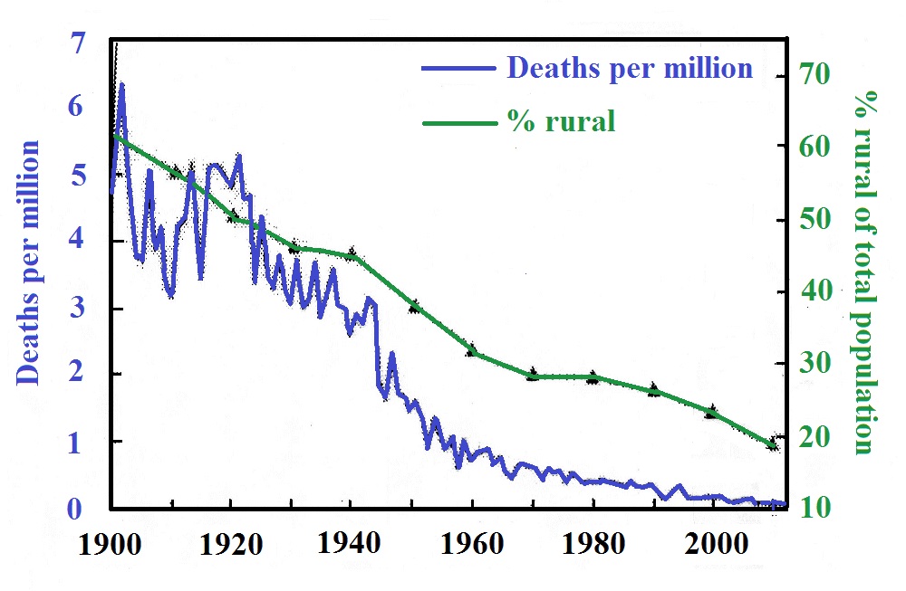
This decrease has largely been due to movement of people from rural to urban locations and into safer homes, workplaces, and schools. An additional reason for the decrease is travel is now almost always inside a vehicle with a metal body (that acts as a Faraday cage). There are about 10 lightning injuries (requiring medical attention) per lightning death.
Source of the image above.
The figure of 6 deaths per million is thought to apply still in regions where large portions of the population live in rural areas with an agriculture based economy.

About 24,000 lightning deaths
occur per year around the globe
(figure above adapted from Holle
(2015))
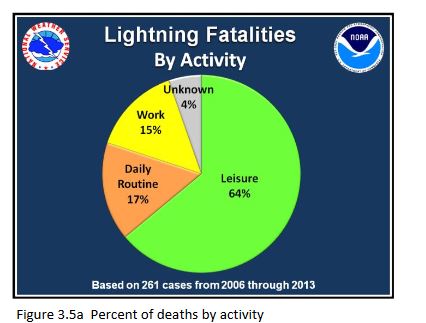
A breakdown of lightning deaths by activity (from Jensenius (2016))
The primary causes of death from lightning are cardiopulmonary arrest and damage to the central nervous system. I had always thought that someone struck by lightning would be seriously burned (internally and externally). This is apparently not the case, the duration of the lightning current is too short. Sometimes a person's clothing catches on fire, however, and that can cause serious burns.
A lightning strike can cause eye damage and hearing loss (one or both eardrums is(are) often ruptured). Psychological effects (anxiety, fatigue, chronic headaches or other pain, personality changes and depression) are apparently a significant and long-lasting result of a lightning strike.
Telephone injury is the most common type of indoors injury associated with lightning.
I would encourage you to read "Updated Recommendations for Lightning Safety - 1998" by R.L. Holle, R.E. Lopez and C. Zimmerman if you ever find yourself in a situation where you might be responsible for providing lightning safety recommendations or warning to a group of people.
You should also be aware of the National Lightning Safety Institute , an organization that is dedicated to providing accurate lightning safety information and interested in lightning safety education.
Lastly I may already have mentioned the The 30/30 Rule but there is no harm done repeating it. Basically if there is less than 30 seconds between a lightning flash and the sound of the thunder, that lightning discharge is close enough to present a risk to you. You should be under cover. You should wait 30 minutes after the last lightning discharge from a thunderstorm before concluding that the storm no longer presents a lightning hazard to you.
The left figure
shows a conventional diode.
The diode begins to conduct when the
forward bias voltage reaches about
0.65 volts. Very little
current flows through the diode when
back biased. The zener diode
at right operates in the same way
when forward biased.
When back biased the diode doesn't
conduct much current until the
voltage reaches a breakdown or zener
voltage (Vz). Then
voltage will be maintained at Vz
over a wide range of currents.
In addition to use as a surge
protective device, zener diodes are
also used as voltage
regulators. Note that a zener
diode is not a bipolar device, it
offers surge protection against only
one polarity of overvoltage.
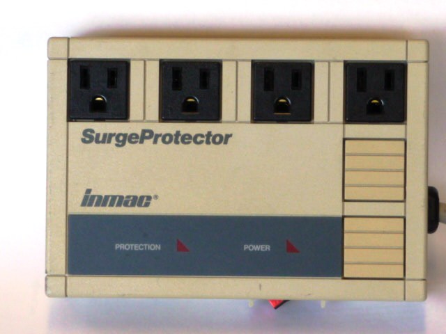
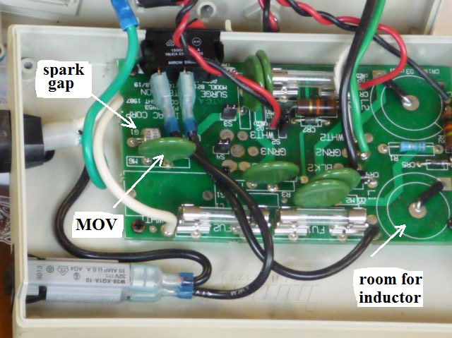
Many of the devices we have been discussing can be found inside a commercial surge protector (in this case an Inmac 8215 Surge Protector)
Finally a few notes from the
chapter on medical issues and personal
lightning safety in Uman's lightning
protection book.Many of the devices we have been discussing can be found inside a commercial surge protector (in this case an Inmac 8215 Surge Protector)
A gas
discharge tube can be seen near
the center left edge of the
printed circuit board (white
ceramic case). A total of
6 MOVs can be seen. They
are green, circular, and might
otherwise be mistaken for
capacitors. There is room
for two inductors on the circuit
board (the two circles printed
on the right side of the circuit
board). The inductors are
apparently not included in this
model.
Despite a large increases in total population, the number of people killed by lightning every year in the United States has dropped by an order of magnitude in the last century or so (from more than 400 per year in the early 1900s to about 30 per year at the present time). The same is true in many other developed countries in the world. The most recent estimates that I could find are summarized below (adapted from Holle (2015)).
This decrease has largely been due to movement of people from rural to urban locations and into safer homes, workplaces, and schools. An additional reason for the decrease is travel is now almost always inside a vehicle with a metal body (that acts as a Faraday cage). There are about 10 lightning injuries (requiring medical attention) per lightning death.
Source of the image above.
The figure of 6 deaths per million is thought to apply still in regions where large portions of the population live in rural areas with an agriculture based economy.
 |
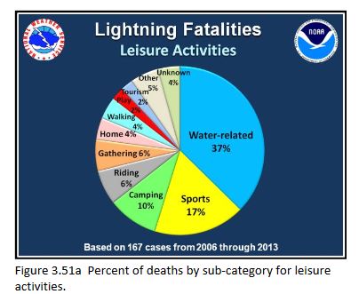 |
A breakdown of lightning deaths by activity (from Jensenius (2016))
The primary causes of death from lightning are cardiopulmonary arrest and damage to the central nervous system. I had always thought that someone struck by lightning would be seriously burned (internally and externally). This is apparently not the case, the duration of the lightning current is too short. Sometimes a person's clothing catches on fire, however, and that can cause serious burns.
A lightning strike can cause eye damage and hearing loss (one or both eardrums is(are) often ruptured). Psychological effects (anxiety, fatigue, chronic headaches or other pain, personality changes and depression) are apparently a significant and long-lasting result of a lightning strike.
Telephone injury is the most common type of indoors injury associated with lightning.
I would encourage you to read "Updated Recommendations for Lightning Safety - 1998" by R.L. Holle, R.E. Lopez and C. Zimmerman if you ever find yourself in a situation where you might be responsible for providing lightning safety recommendations or warning to a group of people.
You should also be aware of the National Lightning Safety Institute , an organization that is dedicated to providing accurate lightning safety information and interested in lightning safety education.
Lastly I may already have mentioned the The 30/30 Rule but there is no harm done repeating it. Basically if there is less than 30 seconds between a lightning flash and the sound of the thunder, that lightning discharge is close enough to present a risk to you. You should be under cover. You should wait 30 minutes after the last lightning discharge from a thunderstorm before concluding that the storm no longer presents a lightning hazard to you.
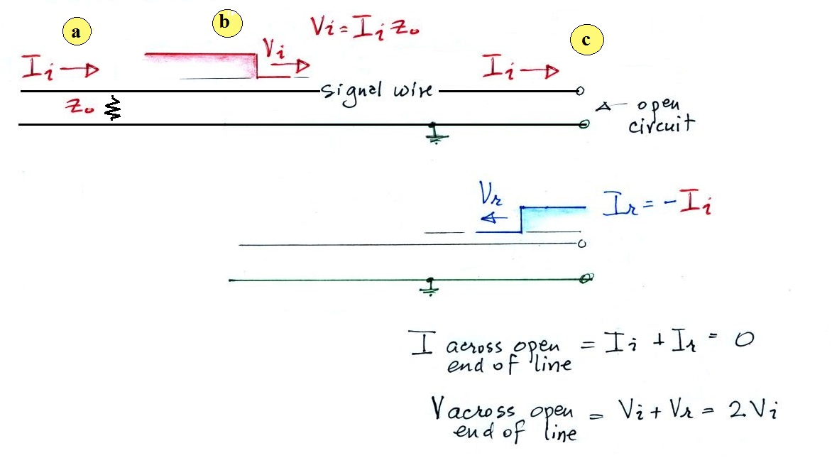
Here's a short look at what happens to a voltage pulse when it arrives at the end of a transmission line. We look first at the case of an open circuit (infinite terminating impedance) at the end of the line.
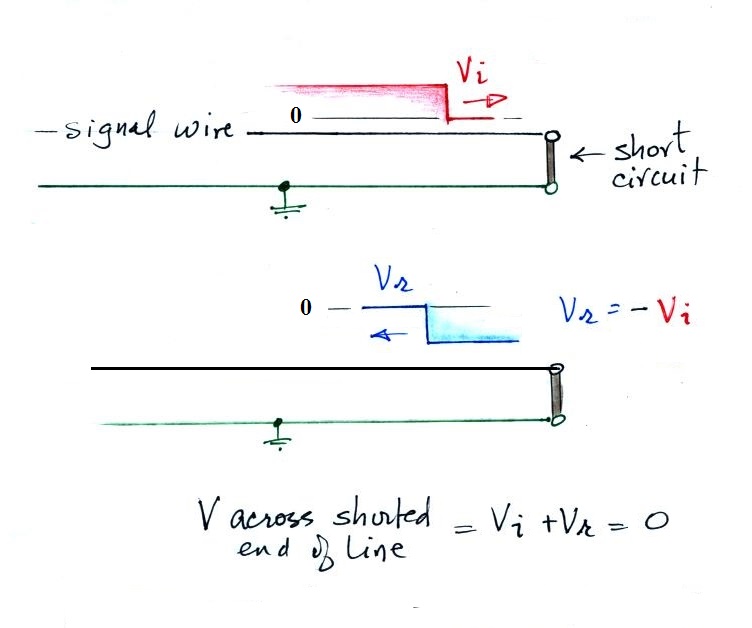
This figure shows the same
voltage pulse, Vi, arriving at the end of a
shorted line. Now the requirement is
that the voltage at the end of the line be
zero. A reflected voltage pulse with the
same amplitude but the opposite polarity is
needed to cancel out the incoming voltage
pulse.
The measured voltage at the end of the line is zero. The current at the end of the line has an amplitude that is twice the incoming current (the reflected current has negative polarity and is traveling from right to left - that is equivalent to a positive current traveling from left to right).
References:
V.A. Rakov, M.A. Uman, M.I. Fernandez, C.T. Mata, K.J. Rambo, M.V. Stapleton, R. Sutil, "Direct Lightning Strikes to the Lightning Protective System of a Residential Building. Triggered Lightning Experiments," IEEE Trans. Power Delivery, 17, 575-585, 2002.
B.A. DeCarlo, V.A. Rakov, J.E. Jerauld, G.H. Schnetzer, J. Schoene, M.A. Uman, K.J. Rambo, V. Kodali, D. Jordan, G. Maxwell, S. Humeniuk, and M. Morgan, "Distribution of Currents in the Lightning Protective System of a Residential Building - Part 1. Triggered-Lightning Experiments," IEEE Trans. Power Delivery, 23, 2439-2446, 2008.
R. B. Standler, Protection of Electronic Circuits from Overvoltages, John Wiley & Sons, New York, 1989 (republished in by Dover Publications, New York, 2002)
R.L. Holle, "Some Aspects of Global Lightning Impacts," 2015 Amer. Meteorol. Soc. Meeting, Phoenix, 2015.
J.S. Jensenius, Jr., "A Detailed Analysis of Lightning Deaths in the United States from 2006-2013," National Weather Service, NOAA, 2016