There were many people in the American
Colonies and Europe that were interested in and actively
studying electricity at the time.
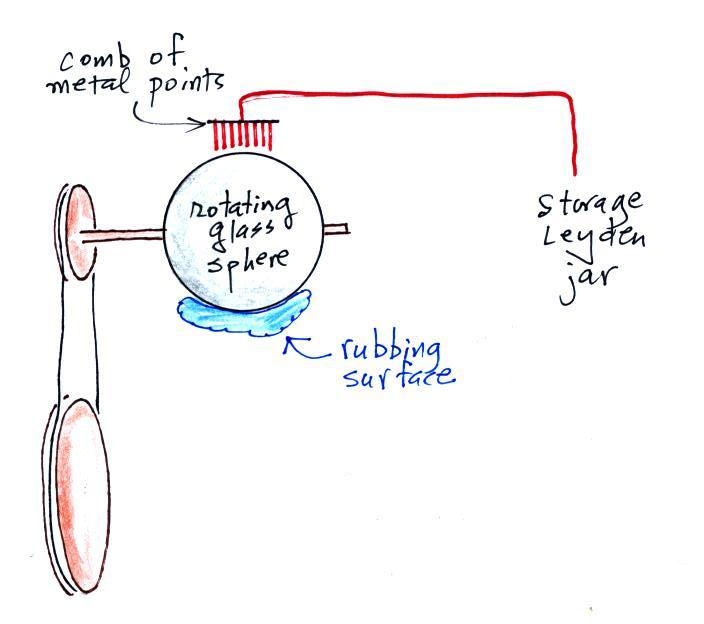
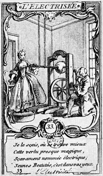
Electrostatic (friction) machines
Electrostatic
machines (friction machines) were in wide
use. Peter Collinson – unpaid
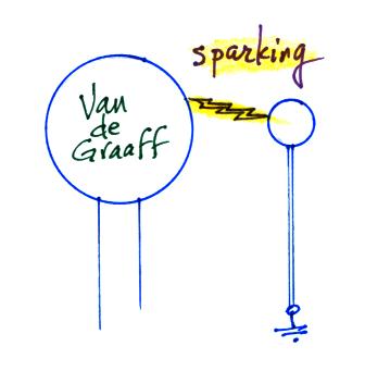
This was demonstrated in class using a
Van de Graaff generator. We first positioned a
grounded metal sphere a few centimeters away from the
generator. Periodically, once sufficient charge built
up on the dome of the generator, an audible & visible
spark (about 3 inches long) would jump to the grounded
sphere.
 |
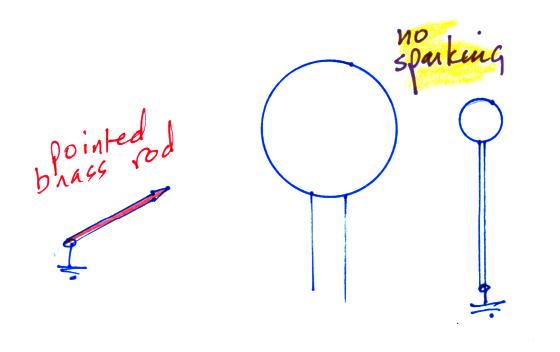 |
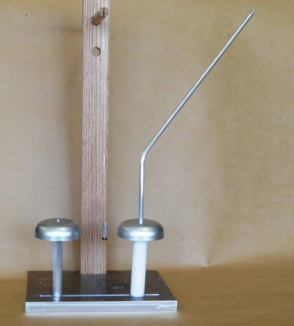
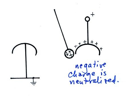
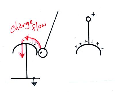
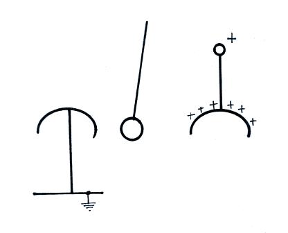
When a pointed, grounded, rod was
brought near the Van de Graaff, the sparking to the grounded
ball stopped. The pointed rod draws off electricity
from the dome of the generator before sufficient charge is
able to build up and spark across to the grounded
ball. Once the pointed rod was moved away, sparking to
the sphere resumed.
Franklin believed (correctly) that rubbing two materials
together did not create electricity. Rather, the
rubbing somehow or another "grabbed onto" and separated
charges that already were part of the neutral
materials. Material 1 might "tear" electrons from
material 2. Material 1 would become negatively
charged and material 2 would be left positively charged.
Priestley explains this more clearly and succinctly:
“Dr.
Franklin
had
discovered … that the electric matter was not created but
collected by friction, from the neighbouring non electric
bodies.” Priestley was the first
historian of electrical science. His
“History and Present State of Electricity” appeared in
 |
 |
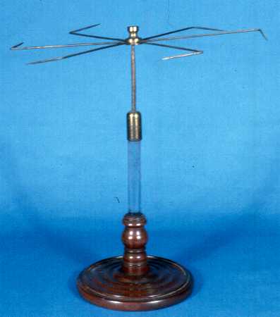
A sketch of this particular Van de Graaff generator is shown below.
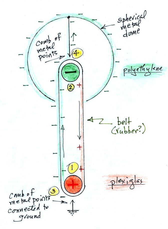
The lower roller (1) is made of
plexiglas. Friction between the belt and the plexiglas
roller causes the roller to become positively charged (the
inside surface of the belt is negatively charged). We
know this from the Triboelectric Series shown below.
A strong electric field develops
between the positively charged plexiglas roller and the comb
of metal points connected to ground. The electric field
is strong enough to ionize the air and corona discharge
"sprays" electrons onto the belt (a wire mesh is positioned
just below the bottom of the belt and is connected to ground).
This charge is then carried upward toward the top of the
generator (3) on the outside surface of the belt. Friction
between the belt and the upper roller (made of
polyethylene) causes the upper roller to become negatively
charged. The negative charge on the outer surface of
the belt is repulsed by the negative charge on the pulley,
the comb draws off the negative charge and moves it to the
surface of the metal dome where it can build up.
We should find that the dome in
this case is negatively charged. Later in the course
we'll use an electric field mill to determine whether that is
really the case. I'm not sure about the fate of the
electric charge on the inside surface of the belt (the surface
that makes contact with the two pulleys).
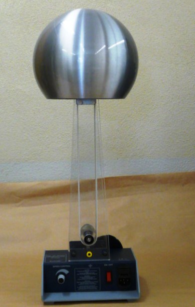
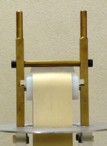
A photograph of a second Van de Graaff generator
demonstrated in class is shown below (source of the
photograph, also available from Active Statics).
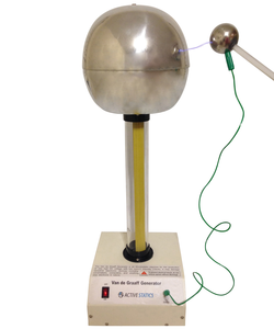
In this case the lower pulley
was polyethylene and the upper pulley was aluminum. That
configuration causes the dome to become positively
charged.
Thus, it is not very predictable, and only broad
generalizations can be made. Amber, for example, can
acquire an electric charge by contact and separation (or
friction) with a material like wool. Other
examples of materials that can acquire a significant charge
when rubbed together include glass rubbed with silk, and
hard rubber rubbed with fur"
And here is list many materials and the charge they acquire (from the same article in Wikipedia). This was on a handout distributed in class.
The Triboelectric Series
| Positively charged (most charging at the top of the list) |
Negatively charged (most charging at the top of the list |
| polyurethane foam Hair, oily skin nylon, dry skin glass acrylic, lucite leather rabbit's fur quartz mica lead cat's fur silk aluminum paper (small positive charge) cotton No charge wool steel |
ebonite silicone rubber teflon silicon vinyl (PVC) polypropylene polyethylene (like Scotch tape) plastic wrap orlon sytrene (Styrofoam - polystyrene foam) polyester synthetic rubber acetate, rahyon gold, platinum brass, silver sulfur nickel, copper hard rubber resins rubber balloon polystyrene sealing wax amber wood (small negative charge) |
This is what was used to determine the charging of the plexiglas and polyethylene rollers in the
Van de Graaff generator
 |
 |
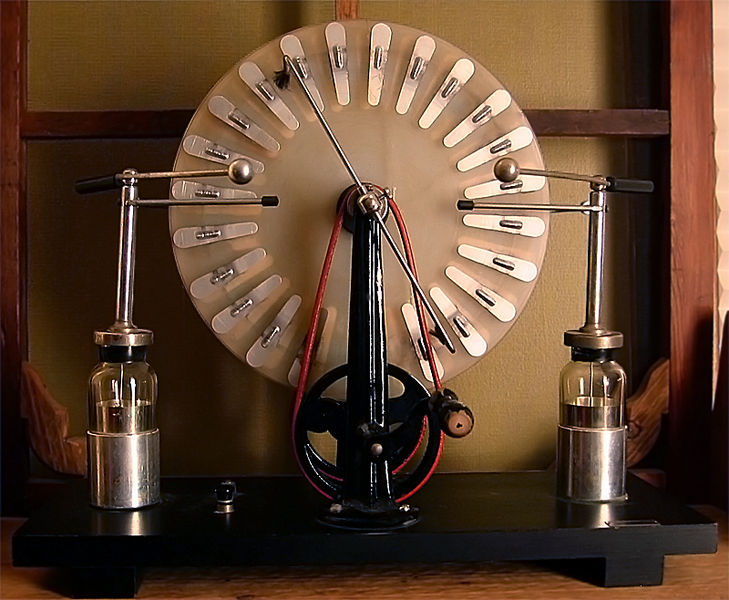
| Note the Leyden
jar capacitors at left and right (photo
from Wikipedia ) |
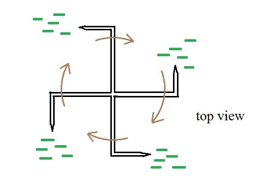
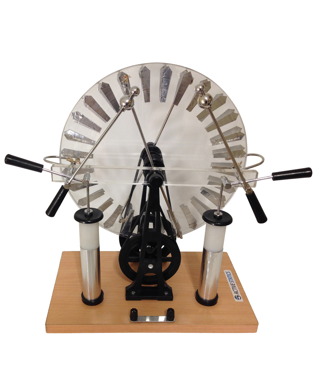
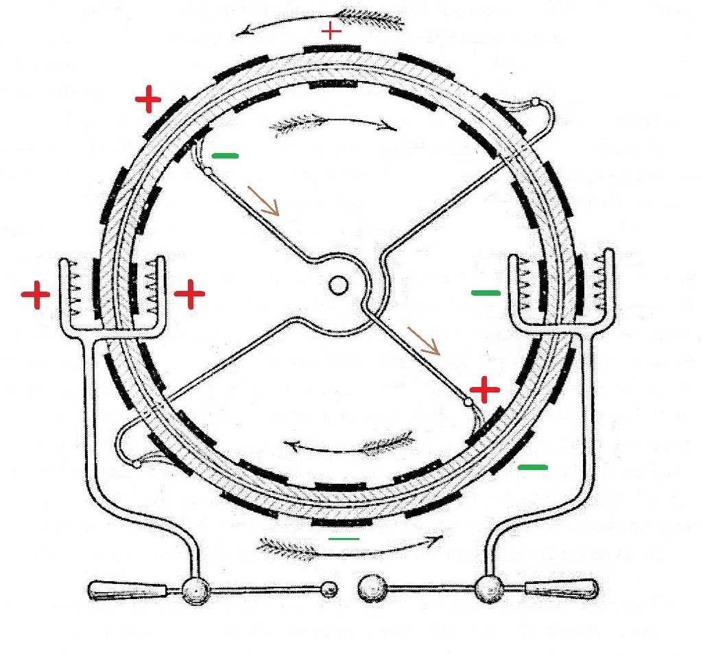
The Wimshurst machine demonstrated in class
(available from Active
Statics) |
 |
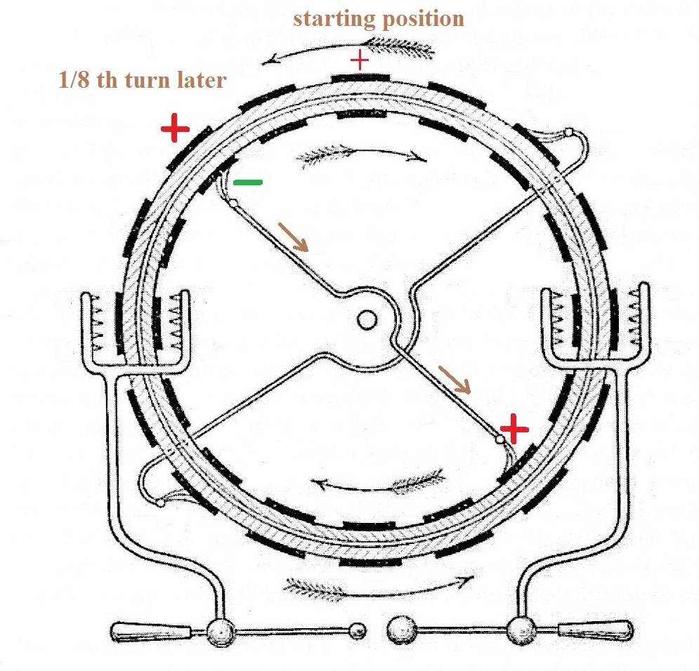 |
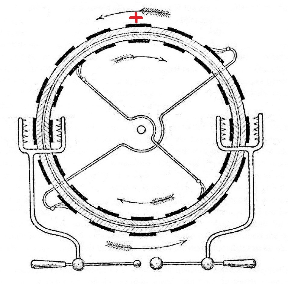
| We imagine that purely by chance a
positive charge is found on one of the metal segments
on the outer cylinder. It could easily have been
a negative charge. This is how the Wimshurst
machine gets started, a charge appears somewhere on
one metal segments. |
The two cylinders, which travel in
opposite directions, have turned 45 degrees.
The original outer positive charge causes negative
charge to be induced in the upper half of one of the
cross members. This results in negative charge
being placed on one of the inner segments.
Positive charge is found on the opposite end of the
cross member and is placed on a segment on the
opposite side of the inner cylinder. |
 |
 |
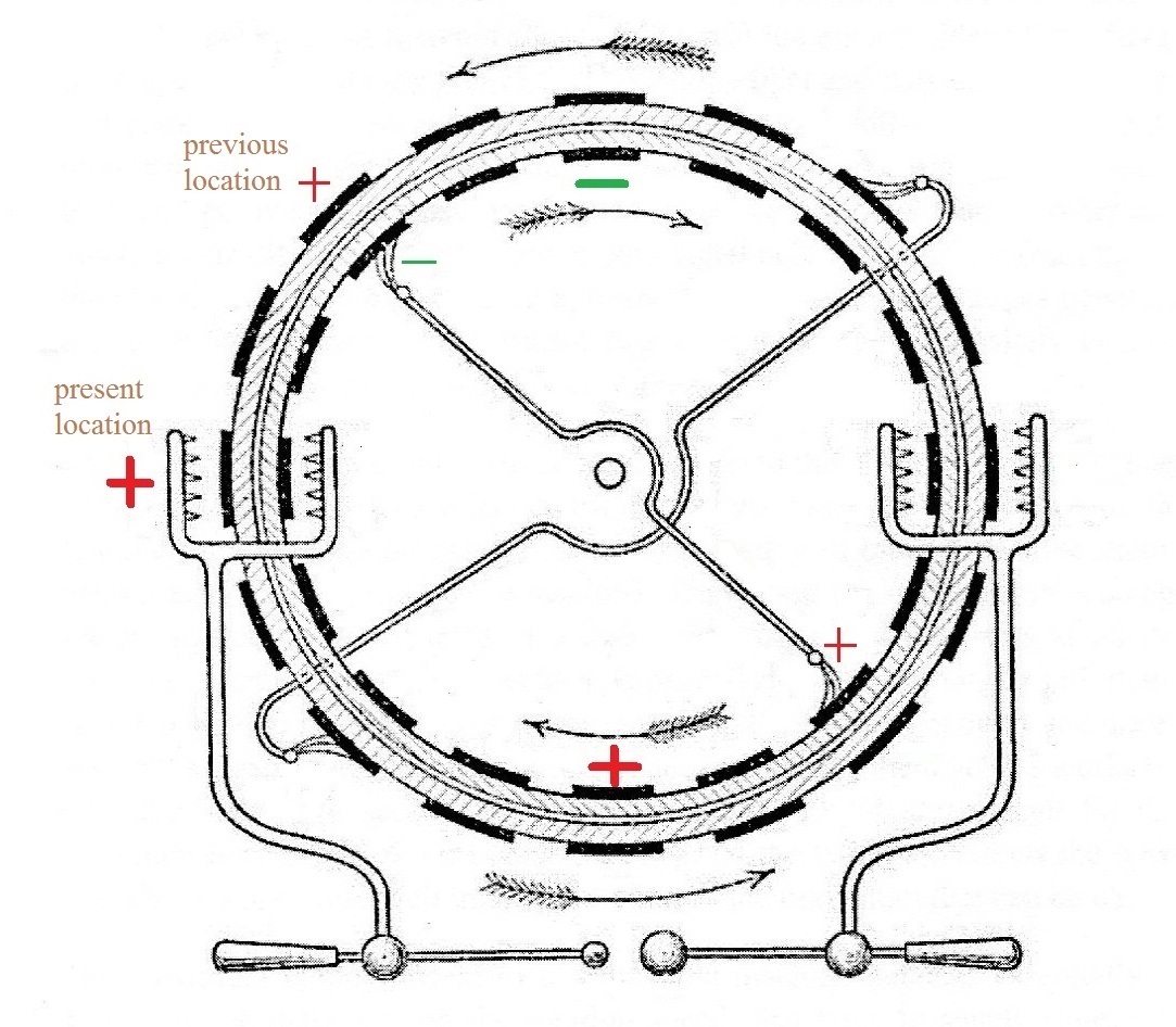
| The cylinders rotate another 45
degrees. The original positive charge is "drawn"
off the outer cylinder at left and stored.
There are two charges left on the inner cylinder. |
The two charges on the inner
cylinder have moved into positions that are in line
with the other cross member. New induced charges
appear on opposite segments on the outer cylinder. |
 |
 |
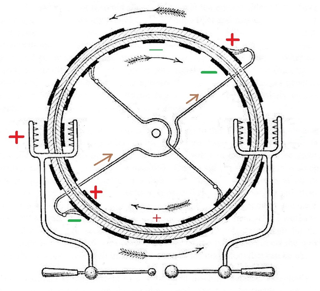
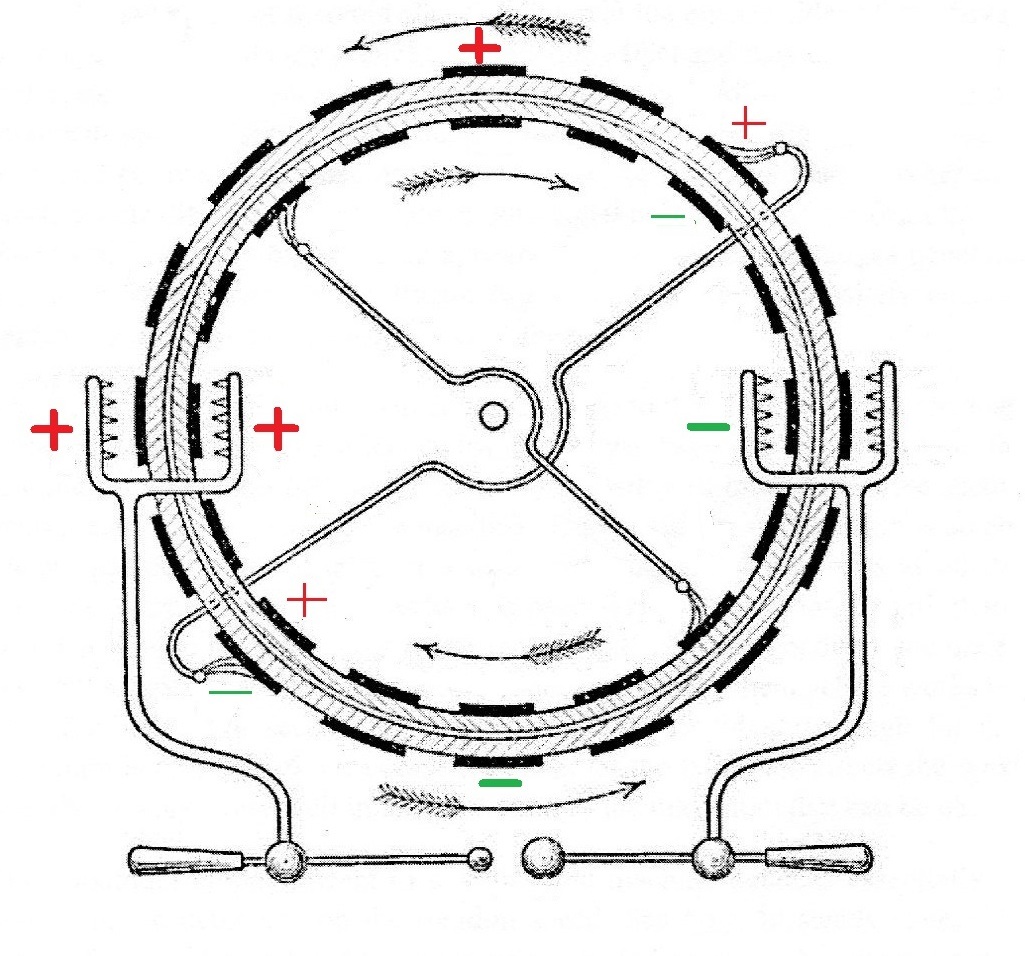
| Negative and positive charge on the
inner cylinder are collected at right and left
respectively. |
Charges on opposite sides of the
outer cylinder cause charges to be induced and placed
on the outer cylinder. Charge will
be collected again at left and right after the next 45
degree turn. |
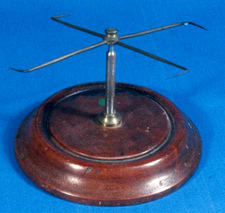
You'll find a short
description (and some explanation) of the experiment
on Wikipedia. A portion is reproduced below
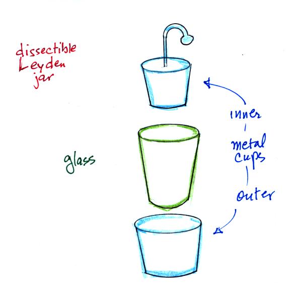
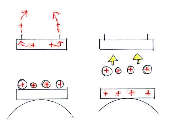
My interpretation of all this is that the charge is stored on the two metal surfaces of the capacitor when it is assembled. Charge moves to the inner and outer surface of the dielectric when the capacitor is disassembled. Once reassembled charge moves from the glass dielectric and back onto the metal plates until the capacitor is discharged.A popular but misleading demonstration with a Leyden jar involves taking one apart after it has been charged and showing that the charge is stored on the dielectric not the plates. The first documented instance of this demonstration is in a 1749 letter by Benjamin Franklin. Franklin designed a "dissectible" leyden jar, shown below, which was widely used in demonstrations.
The jar in the demonstration is constructed out of a glass cup nested between two fairly snugly fitting metal cups. When the jar is charged with a high voltage and carefully dismantled, it is discovered that all the parts may be freely handled without discharging the jar. If the pieces are re-assembled, a large spark may still be obtained.
When not properly explained, this demonstration promotes the myth that capacitors store their charge inside their dielectric. This erroneous theory, due to Franklin, was taught throughout the 1800s, and is still sometimes encountered. However this phenomenon is a special effect caused by the high voltage on the Leyden jar. In the dissectible Leyden jar, charge is transferred to the surface of the glass cup by corona discharge when the jar is disassembled; this is the source of the residual charge after the jar is reassembled. Handling the cup while disassembled does not provide enough contact to remove all the surface charge.
 |
 |
 |