Wednesday Feb. 25, 2015
You probably didn't enroll in this class thinking that you'd be
spending so much time reviewing principles of electricity &
magnetism, learning about small ions, conductivity, Maxwell
currents and that sort of thing. No, you probably thought
(hoped?) the class would be mostly about lightning. And much
of the class will be, beginning with this lecture. We'll
start with a fairly qualitative look at lightning
phenomenology. We'll concentrate primarily on
cloud-to-ground lightning.
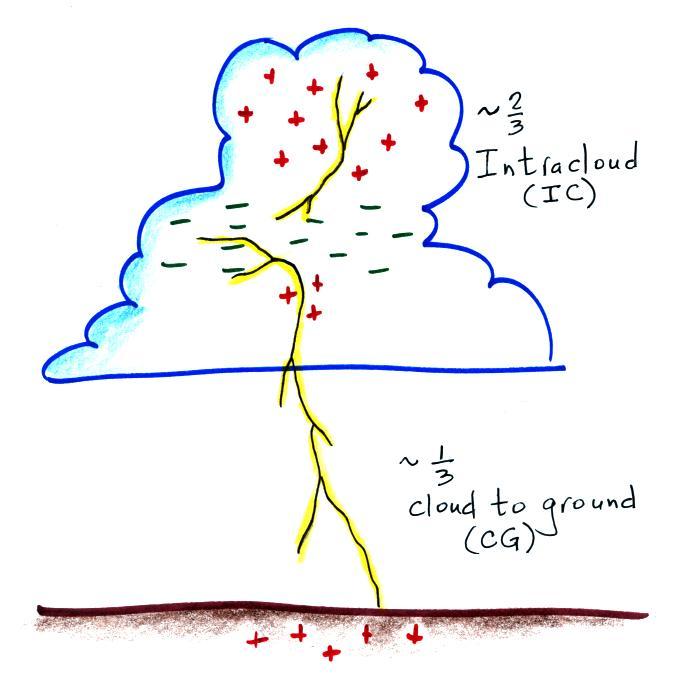
Broadly speaking there are two types of lightning
Intracloud (IC) lightning remains in the cloud and is the most
common type of discharge. Approximately 1/3 of lightning
discharges travel between charge in the cloud and the
ground. We'll use the term cloud-to-ground even though some
relatively rare lightning discharges start at the ground and
travel upward toward the cloud.
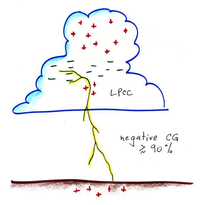
Most CG discharges, "negative cloud-to-ground", carry negative
charge to ground.
Most CG discharges begin with an in-cloud, preliminary
breakdown, process. Also one of the lower positive charge
centers LPCC) is probably involved in the initiation of most
negative CG discharges. One of the interesting and as yet
unsolved problems is how localized fields in the cloud become high
enough to breakdown air (30,000 volts/cm is needed at sea level
altitude, 3 x 10⁶ V/m). Once breakdown is
initiated fields in a larger volume must be high enough for a
discharge to continue to propagate.
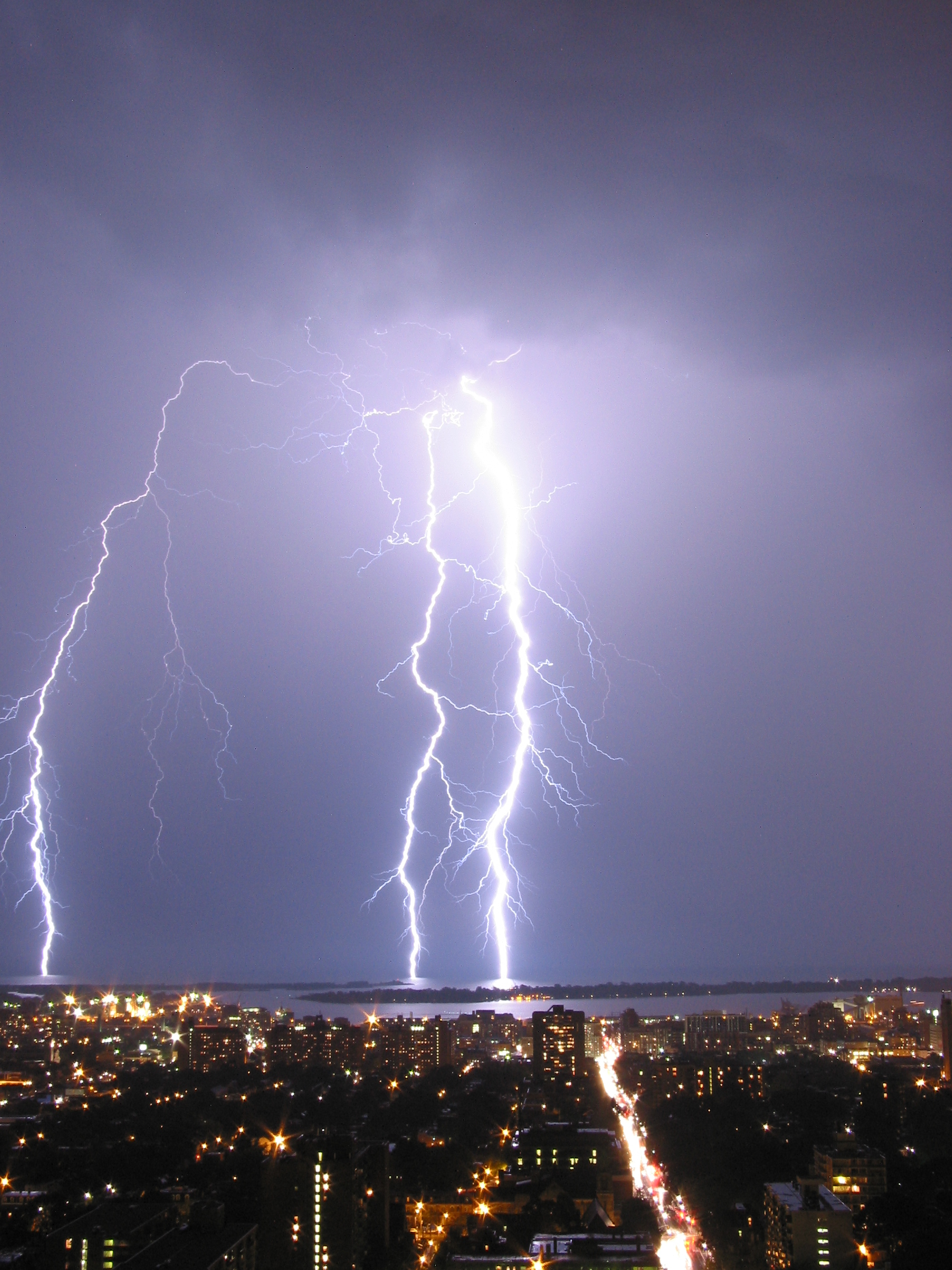
Pay attention to the branching in this and the figures that
follow. The branching tells you the direction of the initial
leader process in the discharge (we'll learn more about the leader
processes shortly). The photograph above is from a Wikipedia article
on lightning.
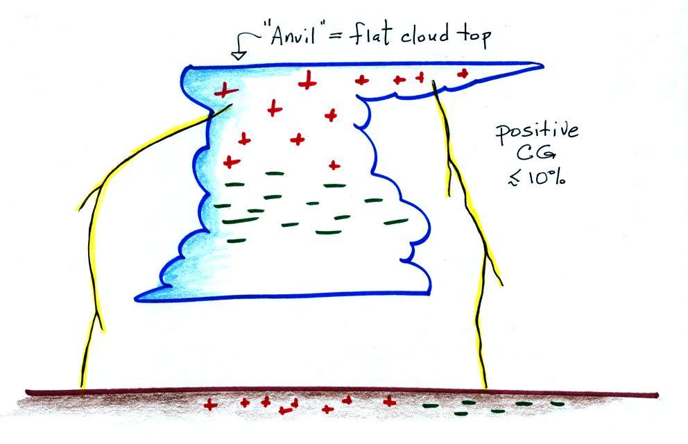
We've mentioned before that some CG discharges begin higher in
the cloud and carry positive charge to the ground. They too
are initiated by a positively charged downward moving leader
process.
Positive CG discharges are more common
(i) in severe thunderstorms where vertical wind shear is
present (faster winds at upper levels than lower altitudes).
Normally the positive charge center is above the main negative
charge and discharge between the two remain in the cloud.
Wind shear can cause the cloud to tilt and move some of the
positive charge away from a position directly above the main
negative charge center. Discharges can then travel from the
cloud to the ground.
(ii) in storms at high latitudes where the
positive charge center is closer to the ground.
(iii) in winter storms. The
positive charge center is closer to the ground. Vertical
wind shear may also be present
(iv) at the ends of summer air mass thunderstorms like we
have in Arizona. The cloud may tilt or the anvil
and positive charge can be blown away from the main body of the
cloud.
(v) in storms with an inverted charge distribution as
discussed in Lecture 12.
Positive CG discharges usually just have a single return stroke
though the return stroke peak current is often very large 100,000
A or more (negative CG discharge peak return stroke currents are
usually 30,000 A or less). The positively charged leader
than initiates a positive CG discharge shows little or no stepping
(we'll discuss the negatively charged "stepped leader" that
initiates negative CG discharges shortly).
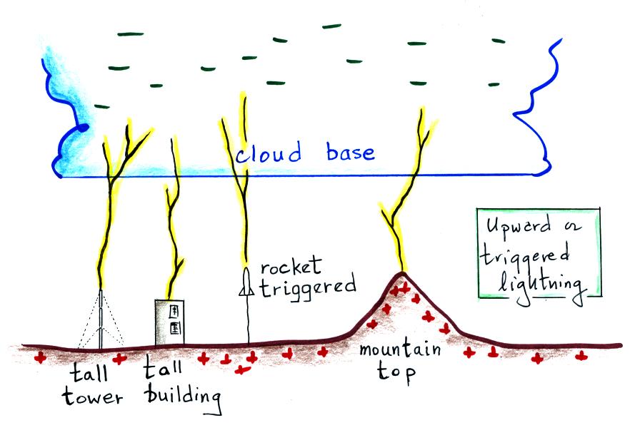
Tall buildings and towers are struck relatively often by
lightning. Often these are discharges initiated or triggered
by the structure itself.
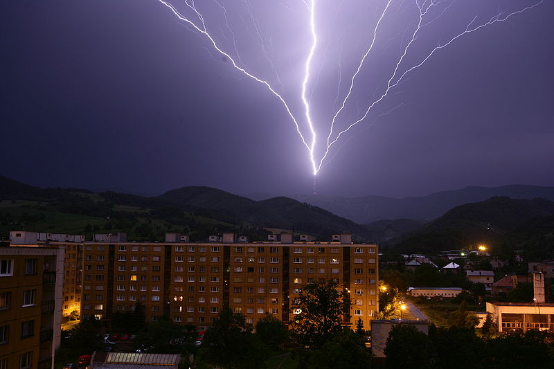
Note the direction of the channel branching. These
discharges begin at the ground with the development of an upward
moving, positively charged, leader (very rarely the
discharge can begin with an upward negatively
charged leader). The upward
leader is followed by downward negatively charged leaders and
upward return strokes, which is, as we shall see, the normal
sequence of events in negative CG lightning. The photo above
shows upward lightning initiated by the Suchá
Hora transmitter tower as seen from Banksa Bystrica, Slovakia, and
is from a Wikipedia
article on lightning.
We saw in an earlier lecture that because they enhance the local
electric field, launch vehicles sometimes trigger and are struck
by lightning. Researchers are now able to trigger lightning
discharges using small rockets. A spool of wire attached to
the base of the rocket unwinds as the rockets travels
upward. If conditions are right, an upward leader is
initiated when the rocket reaches an altitude of 100 m or
so. Direct measurements of lightning return stroke currents
and close (10 meters or less) E and B field measurements can be
made.
Now we'll look in more detail at the sequence of processes that
occur during negative cloud-to-ground discharges.
The discharge begins with some kind of in-cloud preliminary
discharge involving the main negative charge center and one of the
lower positive charge centers. Then a downward moving,
negatively-charged discharge begins moving toward the
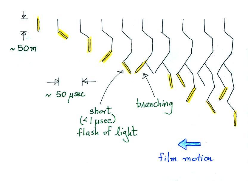
ground. This is called the stepped leader discharge because
the channnel advances in steps of about 50 m length every 50
microseconds or so. The 50 m long channel extensions occur
rapidly (less than 1 microsecond duration) and produce a bright
flash of light. Think of dropping a strobe light from
aircraft altitude and watching it flash on and off as it falls to
the ground.
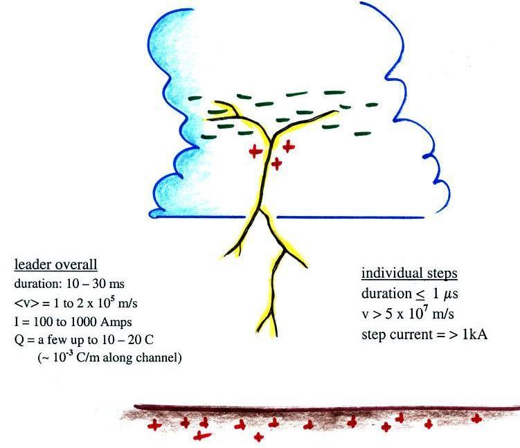
It takes a few 10s of milliseconds for the step leader to
travel a few kilometers from the cloud to near the ground.
This corresponds to an average speed of 1 to 2 x 10⁵ m/sec (traveling from 6 km
altitude in the cloud to the ground in 30 msec would result in a
speed of 2 x 10⁵
m/sec. Negative charge is carried from the main negative
charge center and distritbuted along the length of the leader
channel. Currents flowing in the leader channel range
from 100s to about 1000 Amps.
The individual step, or extension of the leader channel, occurs in
less than 1 microsecond. The velocity of the step is 5 x 10⁷ m/s or faster (50 m in 1 μs
is 5 x 10⁷ m/s)
and the step current is 1 kA or more.
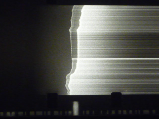
Images of stepped leader have been captured using streaking
cameras (cameras with moving film) and, more recently, on video
cameras with high frame rates. The next figure tries to
illustrate how a descending leader might appear on film.
Because the film is moving (to the left), each of the images is
displaced slightly (to the right) on the film. Extensions of
the channel produce the most light (highlighted in
yellow above) but the remainder of the channel is
usually weakly illuminated. The descending channel breaks up
into brances and then the ends of the separate branches begin to
independently step and move toward the ground.
Here's a short description of the Boys
Camera that was used originally to photograph the sequences
of processes in cloud-to-ground lightning with fast time
resolution. This is from Martin A. Uman's book Lightning
(reissued by Dover Publications, New York, 1984) which has an
excellent survey of early photographic studies of lightning.
Here are a couple images of actual streak camera photographs of a
stepped leader (left) and a dart leader (right). They were
given to me by Dr. Vince Idone a professor at the State University
of New York at Albany.
You can clearly distinquish the separate steps in the upper half
of the left image. We haven't really discussed dart leaders
yet but they travel continuously from the cloud to ground (without
stepping) and at a higher speed than stepped leaders.
You can see some additional examples of streak photographs of
lightning leaders in "Lightning
Leader Characteristics in the Thunderstorm Research
International Program (TRIP)", by R.E. Orville and V.P.
Idone, in an article titled "Novel
Observations of Lightning Discharges: Results of Research on
Mount San Salvatore" by Karl Berger (check the Articles folder for a
complete citation) and in "Progressive
Lightning" by B.F.J. Schonland and H. Collens (published in
the Proceedings of the Royal Society of London and the first of
a series of reports on early lightning research conducted in
South Africa). Here's a short description of
the Boys
Camera that was used originally to photograph the sequences
of processes in cloud-to-ground lightning with fast time
resolution. This is from Martin A. Uman's book Lightning
(reissued by Dover Publications, New York, 1984) which has an
excellent survey of early photographic studies of lightning.
You'll find some additional discussion of streaking photography in
"Lightning
Return Stroke Velocities in the Thunderstorm Research
International Program (TRIP)" by V.P. Idone and R.E.
Orville.
We won't cover the attempts that have been made to understand or
simulate stepped leader channel development. It would be
very difficult to produce a stepped leader discharge in a
laboratory because each step is 50 m long. Here's my
conception of what leads up to an extension of the stepped leader
channel.
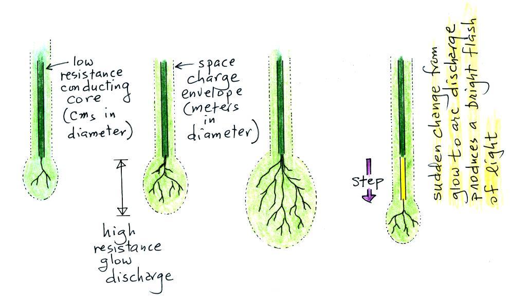
Basically the leader consists of a low resistance arc core that
is surrounded by a space charge envelope. High fields at the
bottom end of the propagating channel create discharge tendrils
that grow out into the air ahead of the leader. Initially
this is a high resistance glow discharge. As the discharge
filaments increase in number and lengthen, more and more current
flows from the bottom end of the arc core. At some point, a
portion of the glow discharge channel will change to a conducting
arc. It is this sudden change from glow to arc discharge
that produces a brief pulse of current and light. This is
the step that effectively lengthens the leader channel.
This seemed like a good point to have a look
at a slow motion video of an actual stepped leader. This first video is a
negative cloud to ground discharge with just a single return
stroke. A video camera that captures 7200 images per second
was used (the video is then slowed down considerably during play
back). And here
is a site with high-speed videos of a negative stepped
leader, a downward positive leader, and an upward positive leader.
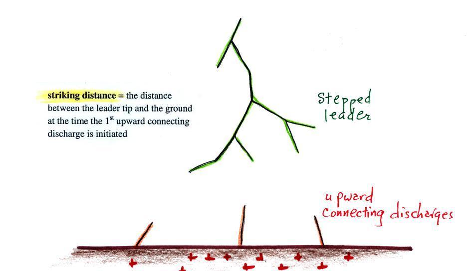
When the stepped leader approaches to within a few hundred meters
of the ground, the electric field at the ground intensifies to the
point that several positively charged, upward propagating
discharges are initiated. One of these will intercept the
stepped leader and determine where the lightning will strike the
ground.
The striking distance referred to in the figure is typically 10 to
20 m above flat ground and 20 to 100 m above taller objects.
This is a reasonably important parameter in the design of
lightning protection design, a topic we will cover later in this
class.
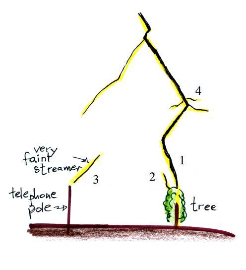
There are probably less than a dozen good photographs of upward
connecting discharges. One of the best was taken by Johnny
Autery in Alabama. The photograph is copyrighted but I've
sketched it below and have pointed out some of the main features.
Not long after the Spring 2013 edition of the class I learned more
about another image. It was taken by Carey Walton and can be
viewed here (click on
the Galleries link at the top of the page and then on Lightning
Gallery 1).
Many of the remaining examples can be seen on pps 141 & 142 in
Rakov and Uman's book "Lightning Physics and Effects." As
chance would have it this portion of the book can be viewed online
here
(you may have to scroll up or down to find pps 141 &
142). There are also some good examples in this gallery
of images.
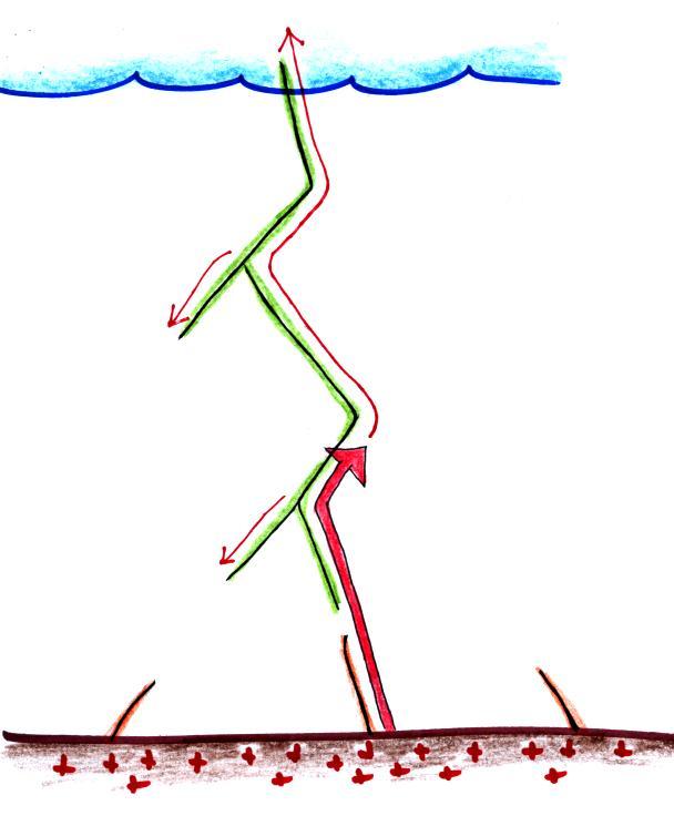
Junction between the upward connecting discharge and the
stepped leader electrically connects charge in the cloud to ground
and a large amplititude pulse of current travels rapidly back up
the channel. This is the first return stroke discharge.
The tip of the return stroke propagates up the channel at a
speed of about 1 x 10⁸ m/s
(1/3 the speed of light) taking about 100 microseconds to travel
from the ground to the cloud. The 1st return stroke has a
peak current of typically 30 kA. Current rises to peak value
in a few microseconds and the peak dI/dt is about 100 kA/us.
The return stroke heats the air to a peak temperature of about
30,000 K (5 times hotter than the surface of the sun). The
overpressure creates a shock wave that quickly decays into a sound
wave that we hear as thunder.
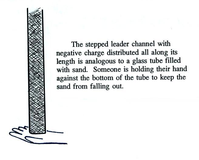
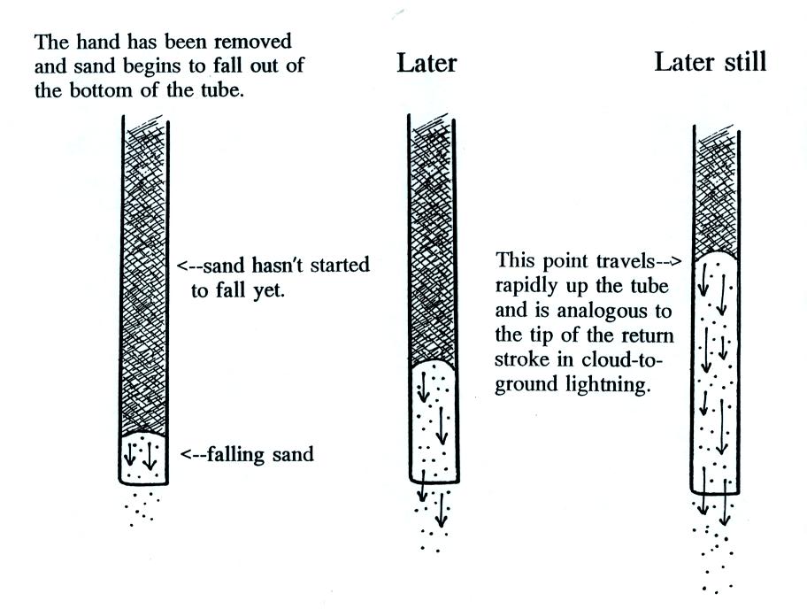
I often use the following analogy to help understand the return
stroke process.
Now imagine what you would see if the hand at the bottom of the
tube is removed.
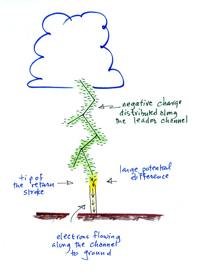
And now back to the stepped leader channel and all the negative
space charge surrounding it.
The intense action is really at the tip of the upward
propagating return stroke. The large potential difference
(cloud potential in close proximity to ground potential) ionizes
the air, creates large currents, heats the air, and produces a
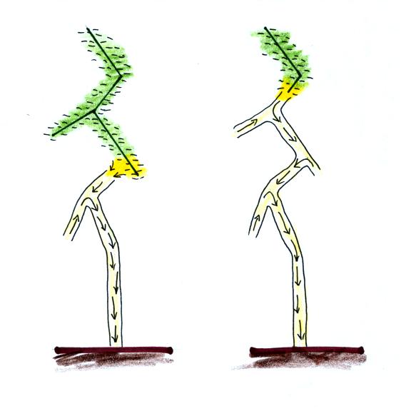
bright flash of light. The potential difference wave can
propagate rapidly up the channel (and out into the
branches). Once the potential wave passes a point on the
channel the space charge envelope collapses and electrons flow
more slowly down the conducting channel to ground.
Some cloud-to-ground discharges end at that point (you'll find
some statistics in our next class). I.e. they consist of (i)
a downward, negatively charged, stepped leader, (ii) a relatively
short upward connecting discharge, and (iii) an upward return
stroke that travels from the ground to the cloud at about 1/3 the
speed of light.
Most cloud-to-ground discharges however contain multiple
strokes. A schematic illustration of a 4 stroke
cloud-to-ground is shown below.
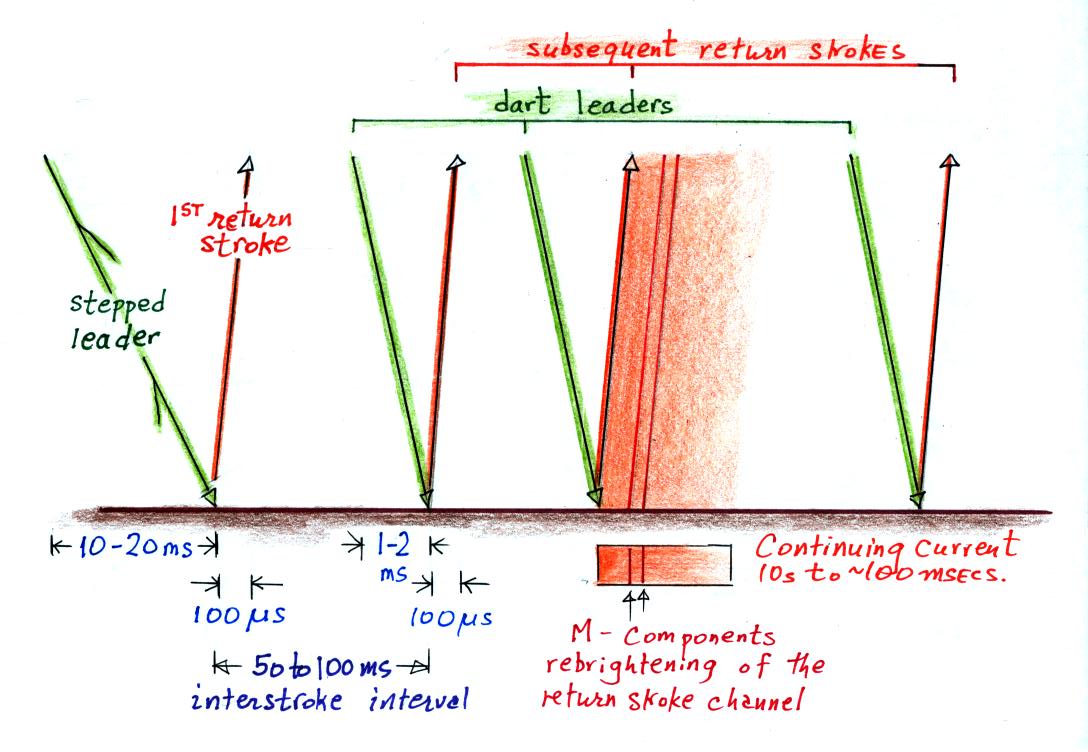
The discharge begins at left in the figure with a branched
stepped leader that is followed by a 1st return stroke.
The stepped leader takes a few 10s of milliseconds to travel
from the main negative charge center in the cloud to the
ground. The ensuing 1st return stroke travels back up the
channel to the cloud is about 100 microseconds.
Then, with a few slight differences, the process repeats
itself. Additional discharges occur typically at
intervals of 50 to 100 ms and are usually preceded by a dart
leader that travels, without stepping or branching, down the
existing main channel. A short upward connecting
discharge is initiated when the dart leader gets close to the
ground and then a subsequent return stroke travels back up the
channel to the cloud. We'll look at the dart leader and
subsequent return stroke processes in a little more detail
shortly.
The 3rd return stroke in the illustration above is
following by a continuing current. This is a low
amplitude (100s of Amperes) current that continues to flow for
10s of milliseconds or more typically, which keeps the return
stroke channel luminous. Short rebrightenings of the
channel sometimes occur during the continuing current, these
are called M-components.
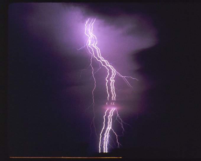
The bright flashes of light produced by multiple return
strokes produces the flickering that you sometimes sees when
observing cloud to ground lightning. If you deliberately
move a camera back and forth while photographing lightning the
separate strokes will be displaced on the image. The
technique is described in an article "Panning for Lightning,"
by John Hendry Jr. that was published in Weatherwise Magazine
(vol. 45, No. 6, pps 18-19, Dec. 1992/Jan 1993
issue). Here is an example (source:
http://www.odec.ca/projects/2005/schu5s0/public_html/lightning.html
).
This appears to have been a 4 stroke flash. The
rightmost channel in the photograph is branched so that is the
first return stroke. Separation of the return strokes
channels like this can sometimes be caused by wind. That
is referred to as "ribbon lightning."