In this lecture and the next we will be covering lightning
protection. We'll
spend today discussing the protection of structures. Then we'll
look at protecting electronics systems from transients created
by lightning. We'll also look briefly at personal lightning
protection.
Much of this lecture and the next are adapted
from material in Uman's The Art
and Science of Lightning Protection (Cambridge Univ. Press,
2008; paperback version 2010). An interesting survey
of the costs of various
types of lightning damage can be found on the first 3 or 4 pages in
Chapter 2. Here are are few examples of the interesting facts and
statistics found there:
The 1977 lightning-caused power blackout in New
York
City cost about $350 million. 30% of
all power failures are due to lightning with an
annual cost close to
$1 billion.
Estimates of the costs of lightning damage to
insurance companies range from 1/3 to $1
billion. In total about 5% of insurance claims involve lightning
(50%
in Florida
in the summer)
30,000 house fires are caused every year by
lightning. About half of the 20,000 wildfires every year
are caused by
lightning. The cost of fighting wildfires was about $1.5 billion
in 2006
(a record
year).
Lightning damage to commercial airlines costs
~$2 billion per year. Damage to military aircraft is comparable.
Lightning causes damage to perhaps 100,000
computers/year.
I do hope that you will look for and better understand and
appreciate some
of the lightning protection that has been installed on buildings in
Tucson and on the UA campus (mainly the newer buildings).
Chances of being struck
We'll use my rental house as an example (the landlord's house is
located next door and was struck by lightning a few years ago).
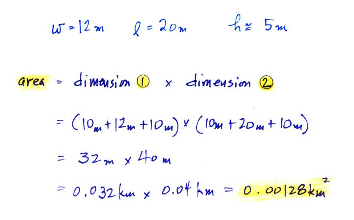
Here is a quick calculation of the chances that the
house might be struck. We'll multiply the effective area of
the house by the lightning flash density for Tucson.
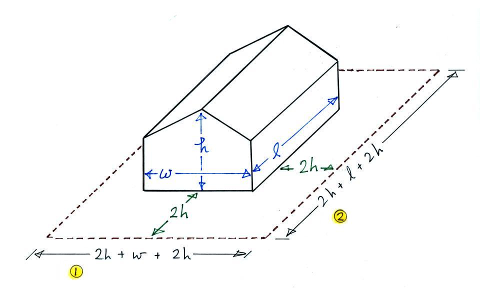
The dimension of the house are
roughly: 20 m long (l) by 12 meters wide (w). The top of the
pitched roof (h) is about 5 m
high. To determine the effective area we must extend the actual
horizontal dimensions of the house by 2 times the height (2 x h) on all
four sides
of the house.
Then
we
multiply
this
area
by
the strike density from the last lecture.
You
would
need
to
question
whether it is worth the expense of installing lightning protection
(especially since I don't actually own the
house).
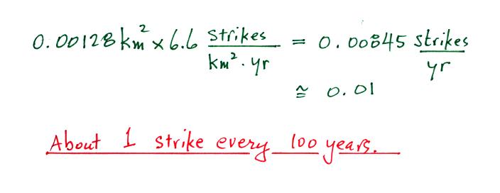
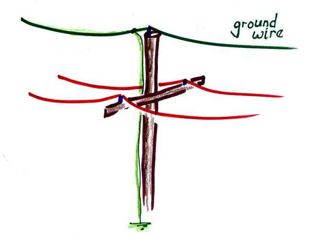
You can do the same kind of calculation for a normal power distribution
line. We'll assume the arms on the power pole that hold the power
lines are 5 m wide and are about 10 meters above the ground. The
effective area of 100 km of line then would be
In this case
some lightning protection is probably advisable. Often a ground
wire will be run above the current carrying wires. Lightning
then
will
hopefully
strike
the
ground
wire
(and
be
safely
carried to ground)
instead of the current
carrying wires.
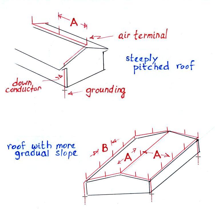
Protection system components
Lightning protection for a house or
building usually consists of 3 components: an air terminal
(lightning rod or Franklin rod), a down conductor, and grounding.
Dimension A in both figures is 20
or 25 feet and is the maximum spacing recommended by the NFPA between
lightning rods. Dimension B in the lower figure is 20 feet and is
the maximum spacing between rods located along the edge of the
roof. Two down conductors at opposite corners of the roof are
shown in the top figure. The bottom figure has a down conductor
at each of the buildings corners.
Solid, low
resistance electrical connections are needed in lightning protection
systems. Here are some
examples of the various connectors that might be used.
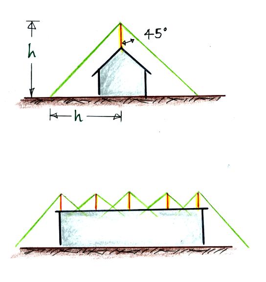
Zone of protection
For structures less than 50 feet tall
Aa lightning rod provides a 45o
or 60ocone of
protection. The 45o cone from a single
lightning rod is shown at top in the figure below.
A larger structure can be protected with
multiple rods with overlapping zones of protection.
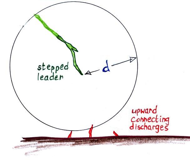
A different approach is used for larger structures. We need
to recall that the striking distance, d, is the distance between
the leader tip and the ground at the moment upper connecting discharges
are initiated. The leader can potentially strike anything withing
a distance d of the leader tip.
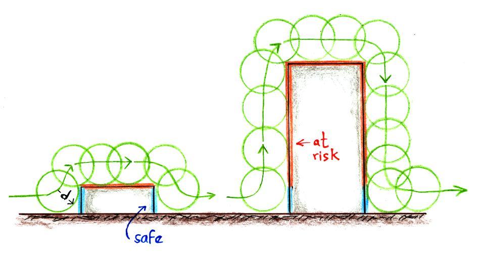
In the rolling sphere method, you imagine rolling a sphere of radius d
(d is the striking distance) over the structure being evaluated for
lightning vulnerability. Parts
of the building touched by the sphere are at risk; those parts of the
building could be struck. Portions that
aren't touched are safe.
The height of the building at
left is less than or equal to d. The sides of the building aren't
touched by the sphere, they've been shaded blue and are safe. The
sphere does touch the top of the building, it is vulnerable.
Lightning protection would
need to be installed on the roof. The building at right is quite
a bit higher than d. Much of the sides as well as the roof can be
struck by lightning. Protection would need to be installed on the
top sides of the building and the roof. Fragments of building
materials knocked off the sides of buildings by lightning are
apparently a serious hazard to people on the street below.
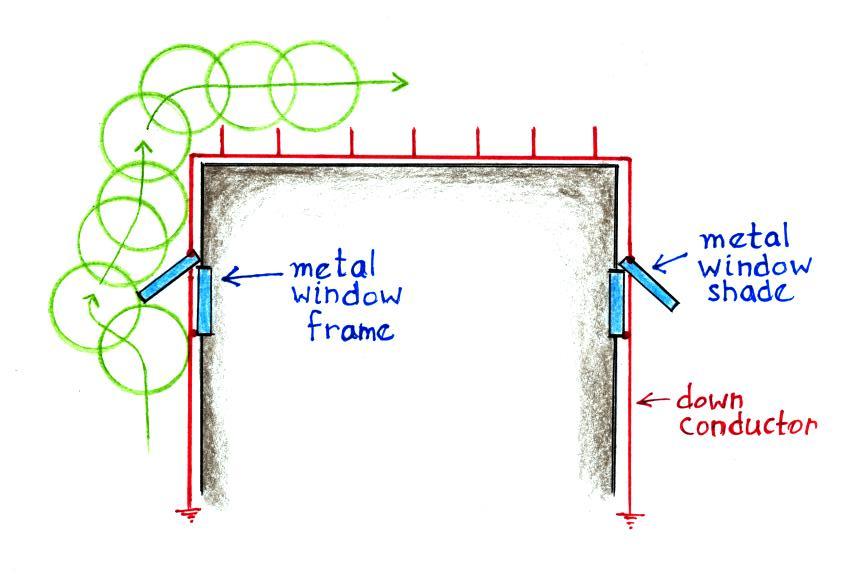
Air terminals could be mounted on the top of a tall buildings.
Additionally, the building designers could make metal window shades and
window frames part of
the lightning protection system by connecting them to the down
conductor.
Note the spacing of the air
terminals must be such that the rolling sphere doesn't touch the roof
in between adjacent lightning rods.
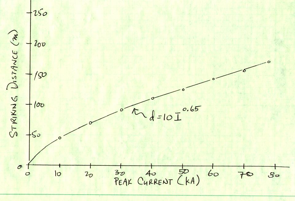
What value of d should be used? Researchers have tried to relate
the striking distance to the amplitude
of the peak return stroke that follows. Generally an expression
of the form
d = A (Ipeak)b
is used. An example
curve is shown below
Recommended values for d for different levels of protection are
given in the table below (based on Table 4.1 in Uman's "The Art and
Science of Lightning Protection").
protection level
d
minimum peak I
% rs>Imin
I
20 m
3 kA
99%
II
30
5
97
III
45
10
91
IV
60
16
84
Level I is the highest degree of protection. With a striking
distance of 20 m, all return strokes with a peak current greater than 3
kA should striking the lightning protection system. This level
would provide protection against 99% of return strokes. The NFPA
recommends a striking distance of 30 m or 46 m.
Interestingly it is the small amplitude return stroke that are likely
to pass in between air terminals and strike a protected building.
We don't really know how common these small return strokes are because
they are below the trigger threshold of most detection systems.
So called "unconventional" rods that use radioactivity or high voltage
to try to initiate an "earlier" upward connecting discharge are
generally not thought to be any more effective than conventional
"Franklin" rods.
A wire mesh covering
the roof of a building or vulnerable installation
on the ground can be used instead of lightning rods. A wire mesh
covered the administration trailer at the rocket triggered lightning
site in Florida for example.
The following table gives recommendations for the spacing of the wires
in a wire mesh (based on Table 4.2 in Uman's "The Art and Science of
Lightning Protection")
protection level
d
mesh spacing
I
20 m
5 m x 5 m
II
30
10 x 10
III
45
15 x 15
IV
60
20 x 20
A metal roof
also provides good protection from lightning. The NFPA recommends
that the roof be at least 3/16 inch thick.
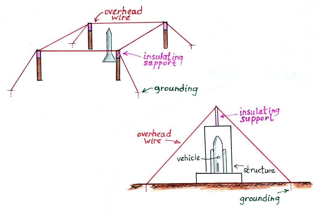
Overhead
wires are used to protect launch installations at the Kennedy Space
Center
The
insulated support on the figure at lower right is on the structure and
not directly overhead the launch vehicle.
Down
conductors
Air terminals should be connected to as many
down conductors as possible. Lightning rods on a house should be
connected to at least two down conductors (at opposite corners of the
house for example).
There are several reasons for this:
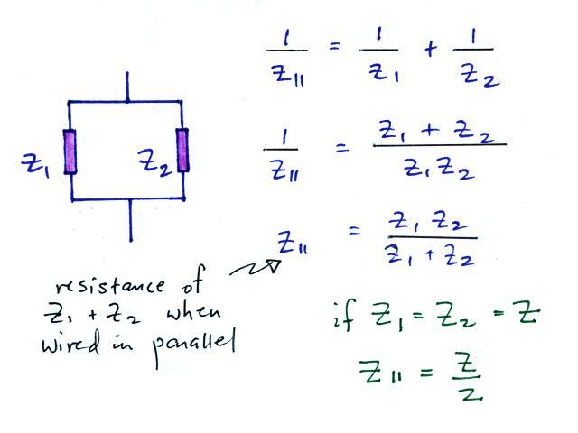
(i) The down conductor will have some
resistance and impedance. Connecting inductors or
resistors in parallel reduces the combined impedance.
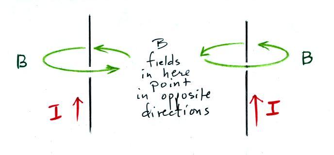
(ii) The B fields from two down
conductors positioned on opposite sides of
a building will point in opposite directions in the interior of the
building. This will reduce the strength of the B
fields inside the structure and reduce the intensity of voltages and
currents induced in electronic circuits inside the building.
The recommended minimum crossectional area
for down conductors is
about 50 mm2 for
copper(that correcponds to a radius of 4
mm, a diameter of 8 mm or roughly 1/3 inch)
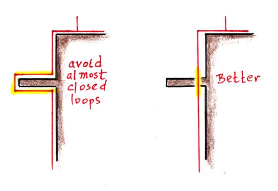
Almost closed loops on the down
conductor should be avoided. This adds impedance and sparks are
likely to jump across adjacent points on the down conductor.
Rather than going around a protrusion on
a building wall, it would be better to go through the protrusion and
keep the down conductor as straight as possible.
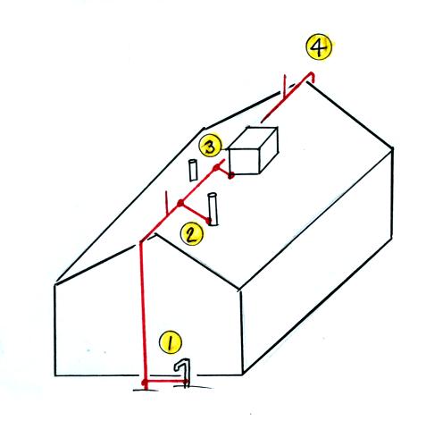
If a lightning protection system is
struck it can easily rise to a
potential of a few megavolts (see the discussion at the beginning of
Lecture 16). The down conductor should be
"bonded" to
(electrically connected to) metallic objects within about 5 m
to prevent sparking from the down conductor to nearby metallic
objects. In the figure below (my rental house
again) the down conductor has been connected to
a water faucet at (1), to a vent pipe at (2), and to an
evaporative cooler at (3). A second down conductor extends from
the roof to ground at Point 4.
Here are typical fields needed for spark initiation and
propagation:
3 x 10⁶
V/m is need to breakdown air at
sea level
500 kV/m is the average field needed for propagation of negative
polarity leaders
300 kV/m is the average field needed for positive leader propagation.
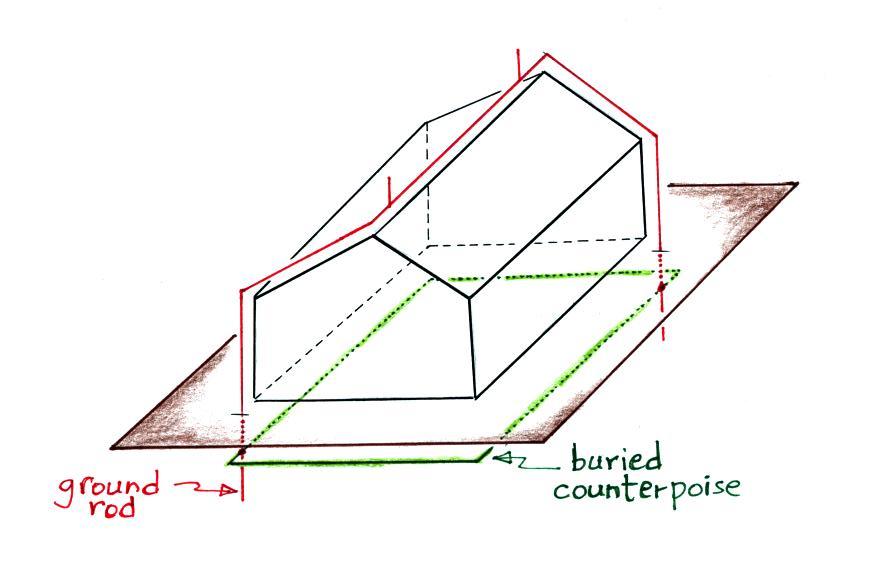
Grounding
Grounding rods are generally copper clad steel and should be at
least 8 feet long. The
bottom end should be at least 10 feet deep.
Grounding can be improved by connecting grounding rods to a
counterpoise, a loop of grounding wire that encircles the
structure. This reduces potential differences inside the loop.
The grounding can be also be connected
to a buried mesh under the structure or to interconnected rebar in the
concrete base of the structure. This is well illustrated in an article by V.A.
Rakov "Lightning Protection of Structures and Personal Safety."
Here is a table of resistivities of various materials (Table
5.1 in Uman's "The Art and Science of Lightning Protection").
Material
Resistiviy in ohm-meters
ocean water
0.1 - 0.5
ground, well & spring
water
10 - 150
lake & river water
100 - 400
rain water
800 - 1300
commercial distilled water
1000 - 4000
chemically clean water
250000
clay
25 - 70
sandy clay
40 - 300
peat, marsh &
cultivated soil
50 - 250
sand
1000 -3000
moraine
1000 - 10000
ose (calcereous remains)
3000 - 30000
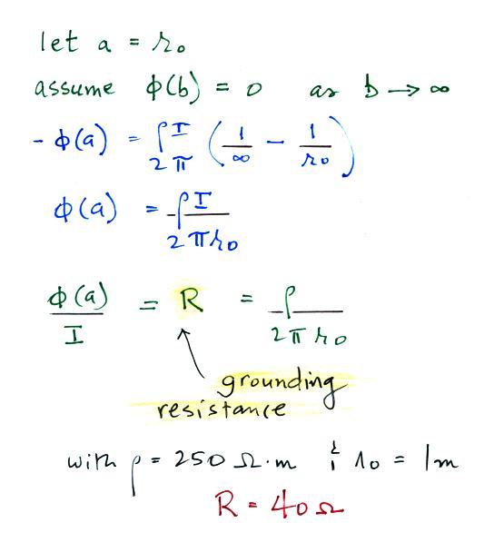
Resistivity is not the same thing as grounding resistance.
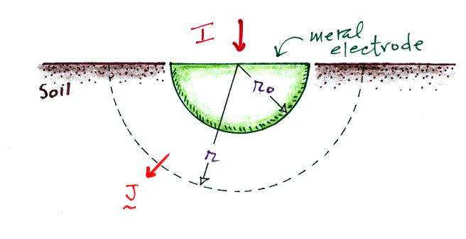
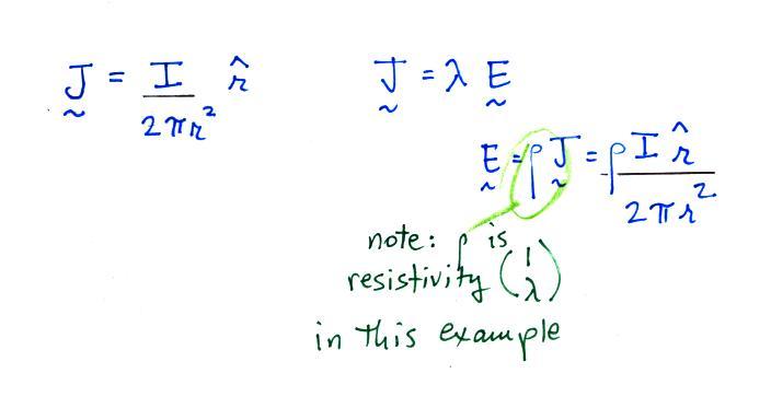
We'll do a relatively straightforward calculation of
grounding resistance. The rather unusual geometry is
shown above and will make the calculation manageable. A current I
is injected into a hemispherical piece
of metal that is buried in soil.
We'll assume that the current
spreads out evenly in the soil. We divide I by the area of half a
sphere to determine the current density J.
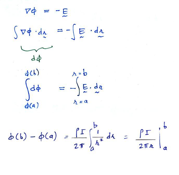
Now that we have an expression for E, we can determine the
potential.
We'll determine the potential
difference (voltage) between a point deep in the soil (r = b) and a
point
close to the grounding electrode (r = a).
Here's the remainder of the calculation. A grounding
resistance of 40 ohms would be pretty good for Tucson.
Computing the grounding resistance of grounding rods or buried
cables would be more difficult. So we'll just cite two additional
tables (Tables 5.2 and 5.3) from Uman's book. These give ground
resistances of a 1/2 diameter vertical grounding rod and a 1/2
inch diameter buried horizontal wire as a function of conductor length
and soil resistivity
(100 ohm-meter is relatively a relatively soil conductivity, 1000 ohm
meter is relatively
poorly conducting soil).