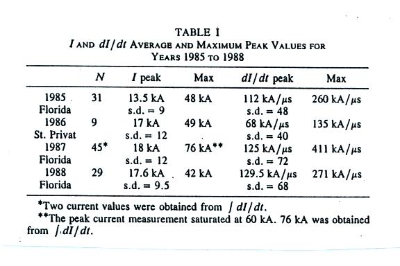
This first figure gives mean peak I
and peak dI/dt values from rocket triggered lightning experiments
conducted in Florida (at the Kennedy Space Center) and at the Saint
Privat d'Allier station in central France. With the exception of
the 1986 St. Privat dI/dt data (where I seem to remember there was a
problem with the dI/dt sensor), the mean values from the different
summer field experiments are generally in pretty good agreement.
I computed an overall average peak I value of 16.6 kA and a peak dI/dt
value (France 1986 data omitted) of 122 kA/us. Remember that
return strokes in triggered lightning are thought to be comparable to
subsequent return strokes in natural lightning.
Lightning current parameters such as peak I and peak dI/dt are often log-normally distributed. Data that are log-normally distributed should fall in a straight line on a cumlulative probability plot. Cumulative probability distributions of peak I and peak dI/dt from the Florida 1987 and 1998 experiments are shown below (only the top figure was on the handout distributed in class).

Lightning current parameters such as peak I and peak dI/dt are often log-normally distributed. Data that are log-normally distributed should fall in a straight line on a cumlulative probability plot. Cumulative probability distributions of peak I and peak dI/dt from the Florida 1987 and 1998 experiments are shown below (only the top figure was on the handout distributed in class).
Parameters from these distributions
are summarized in the table below together with parameters from the
Swiss and Italian tower measurements.
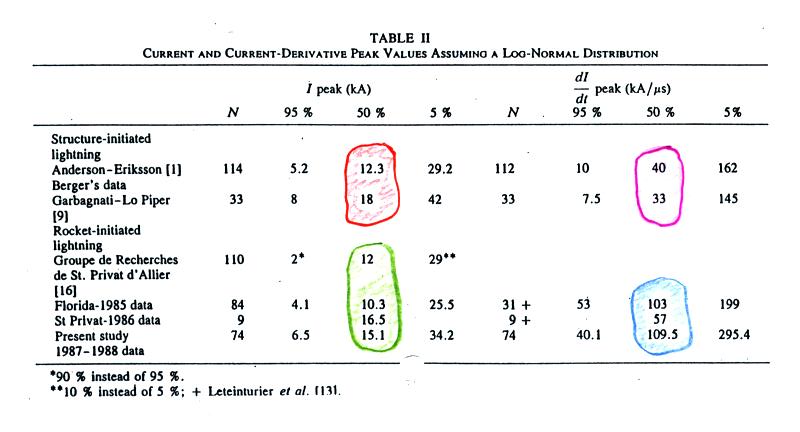
Generally the 50% values (the median) of peak I from the tower measurements (circled in orange) compare very well with the peak I values from the rocket triggered lightning experiments (circled in green).
I might have mentioned earlier that the sensors and recording equipment used in Switzerland and Italy probably didn't have fast enough time resolution to accurately measure peak dI/dt values. The data in the table above seem to reflect this. The tower derived measurements (40 and 33 kA/us and circled in pink) are significantly lower than the values obtained during the triggered lightning experiments (103 and 109.5 kA/us, circled in blue). We should probably disregard the 57 kA/us value from the St. Privat 1986 campaign.
Now the main topic of the day learning how certain lightning return stroke current characteristics might be estimated from remote measurements of electric and magnetic fields radiated by lightning. This will first involve learning something about the fields radiated by lightning and about how return stroke currents might vary with time and altitude along the lightning channel.
First here's the geometry used in
the E and B fields calculation. We aren't going to look at the
details of the calculation, I'll simply write down the results.
If you are interested in the details have a look at the Uman, McLain,
and Krider (1975) in the class articles folder.

The expression above gives the
electric field radiated by a short
segment dz located at an altitude z above the ground. At that
ground the E field has just a z component.

I should mention there is a small error in the expressions above. This won't affect our discussion, but if you would like to see the correct expressions, click here.
We won't really be using these rather complex general expressions very much. Rather let's just note that the electric field expression contains terms involving a time integral of current, the current itself, and a term with the time derivative of the current.

We refer to these are the electrostatic, induction, and
radiation field components. The B field has just induction and
radiation field components.
The electrostatic field is generally dominant at close range. Because it decreases as 1/R, the radiation field is the only field component observed at long range (beyond a few 10s of kilometers). Also because peak dI/dt occurs very early in a return stroke discharge, the radiation field also dominates at the very beginning of a return stroke.
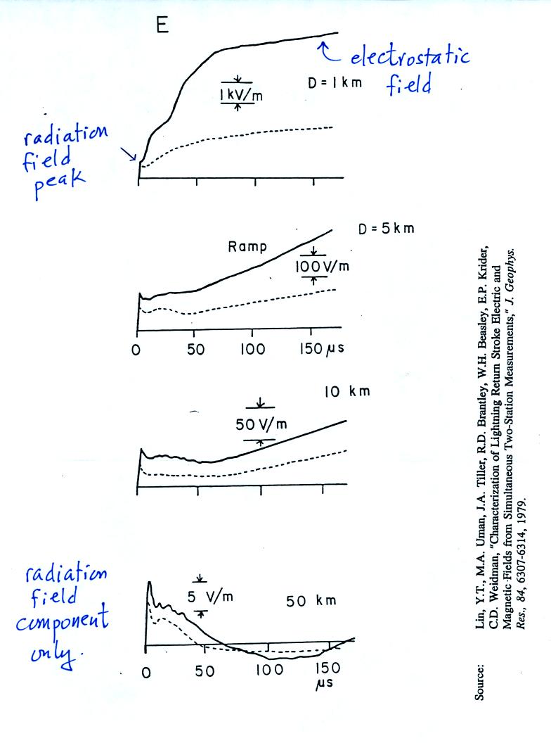
The figure below is an attempt to sketch the shapes of the 3 field components.

The solid lines show typical first return field values, the dotted
lines are for subsequent strokes. These aren't actual waveforms,
but they are based on measurements of actual waveforms (lots of
waveforms).

The hump is probably coming from the induction field. We don't see it on E field waveforms because the electrostatic field component is bigger. B fields don't have a magnetostatic field component.

The B field has just an azimuthal
component.
There is some interest in how
lightning E and B fields couple onto electric power lines. To
properly examine this problem you would need to compute E and B for
points above the ground (at the level of the power lines). That
becomes a more complicated problem because the E and B fields will each
have 3 components (vertical, radial, and azimuthal components in
cylindrical geometry).
I should mention there is a small error in the expressions above. This won't affect our discussion, but if you would like to see the correct expressions, click here.
We won't really be using these rather complex general expressions very much. Rather let's just note that the electric field expression contains terms involving a time integral of current, the current itself, and a term with the time derivative of the current.
The electrostatic field is generally dominant at close range. Because it decreases as 1/R, the radiation field is the only field component observed at long range (beyond a few 10s of kilometers). Also because peak dI/dt occurs very early in a return stroke discharge, the radiation field also dominates at the very beginning of a return stroke.
The figure below is an attempt to sketch the shapes of the 3 field components.
And here are examples of E and B
waveforms (on a class handout) that you would expect to see at various
distances from a CG stroke (these were on a class handout)
The hump is probably coming from the induction field. We don't see it on E field waveforms because the electrostatic field component is bigger. B fields don't have a magnetostatic field component.
Listed above are some of the
approaches that have been taken to
try to determine I(z,t). We will mostly be concerned with the 3rd
approach.
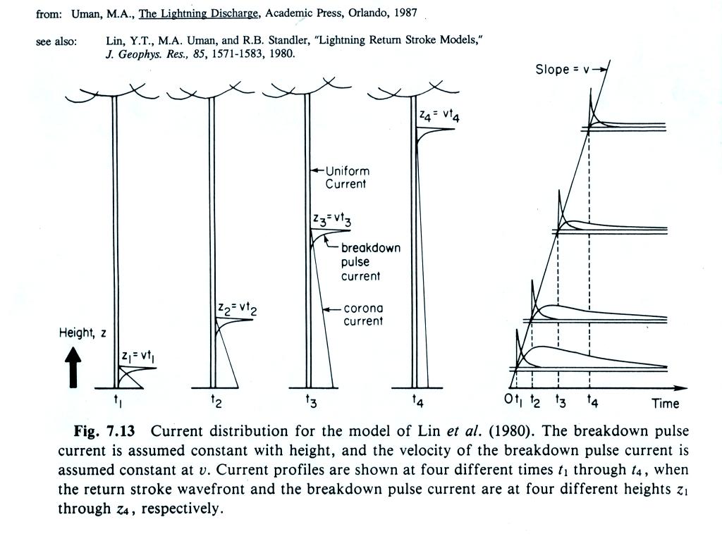
Bruce Golde Model

In the Bruce Golde model the return stroke current is assumed to
be uniform along the length of the channel. The lightning current
changes with time but there is no variation along the length of the
channel. This is illustrated in the figure below.

The current waveform measured at the ground is shown at the bottom
of the figure. Current amplitude along the length of the channel
is shown above. As current changes at the ground, it also changes
simultaneously along the entire length of the channel. This is
physically unreasonable as it would require that information propagate
along the length of the channel at infinite speed.

Bruce Golde Model
Here is first an expression for the
radiation field component of
the electric field at a distance D from the lightning stroke.
There are a few tricks involved in this derivation (that we won't worry
about) because the current is discontinuous at the top (tip) of the
upward propagating return stroke current. The expression for E
can be inverted to give the channel base current as a function of
the field.
Transmission Line Model
In the transmission line model the current waveform measured at the ground is assumed to propagate up the channel without changing shape and at constant speed.

Transmission Line Model
In the transmission line model the current waveform measured at the ground is assumed to propagate up the channel without changing shape and at constant speed.
Here's how that is expressed in
functional form. Basically the current value observed at height z
at time t is the value recorded at a time t-z/v earlier (i.e. the time
it took to travel from the ground up to height z).

And here's an illustration of what
this would look like. The current waveform measured at the ground
basically just propagates up the channel at constant speed.


We'll make a couple of simplifying
assumptions.
The partial derivative with respect
to time can be replaced with a partial with respect to z. This
makes it easy to integrate over z.

H is the height of the return
stroke channel. The first term in brackets is zero at times less
than H/v.


You couldn't ask for a simpler
relationship between E and I (or dE/dt and dI/dt)

We had time to look at one of the
experimental tests of the Bruce Golde (BG) and Transmission Line (XL)
models.
Measurements of electric and
magnetic fields were
measured at 2 stations: one close to and the other far from the strike
point. The far field measurements (which are just radiation
fields
and don't contain any induction or electrostatic fields) were used to
determine the return stroke channel current, I(t), using of the two
equations above. Then both near and far fields were calculated
and compared with the
actual measurements at the two sites.
Here are some of the results from the tests (on class handouts). These data are from a publication by Lin, Uman, and Standler (1980). You'll find a link in the class articles folder.

The experimental tests used only the fields from subsequent strokes (1) because, without branches, they are closer to the model assumptions that the lightning channel is straight and vertical. A constant return stroke propagation speed was assumed and was adjusted to give the best fit between measured and computed fields.
At (2) the distant measured radiation field is used to derive the Bruce Golde (BG) and Transmission Line (TL) model return stroke current I(z,t). Then the E radiation fields are computed using both the BG and TL currents. You can see for the distant fields, the agreement is pretty good but not perfect. In particular the XL calculated field never goes below zero.
The agreement isn't quite as good for the close fields (3).
The derived channel currents are shown in (4). The TL current waveform is too narrow and is unrealistic.

Here are some of the results from the tests (on class handouts). These data are from a publication by Lin, Uman, and Standler (1980). You'll find a link in the class articles folder.
The experimental tests used only the fields from subsequent strokes (1) because, without branches, they are closer to the model assumptions that the lightning channel is straight and vertical. A constant return stroke propagation speed was assumed and was adjusted to give the best fit between measured and computed fields.
At (2) the distant measured radiation field is used to derive the Bruce Golde (BG) and Transmission Line (TL) model return stroke current I(z,t). Then the E radiation fields are computed using both the BG and TL currents. You can see for the distant fields, the agreement is pretty good but not perfect. In particular the XL calculated field never goes below zero.
The agreement isn't quite as good for the close fields (3).
The derived channel currents are shown in (4). The TL current waveform is too narrow and is unrealistic.
An additional set of test results.

A return stroke velocity was assumed for each set of near and far
E and B field measurements (the velocity value was adjusted to give the
best fit between measured and calculated fields). The velocity
values derived for the BG model are shown in the top graph and appear
to be distance dependent (distance from the close station to the
lightning strike point). That is a physically unreasonable
result. The velocities derived for the TL model appear in the
bottom plot. The values are reasonable (perhaps a little lower
than the 1 x 10⁸ m/s commonly
assumed for return strokes) and do not
appear to vary
with distance.

Here are the peak current values derived for both the TL and BG
models. In both cases peak current values appear to be distance
dependent which is not realistic. Many of the TL peak currents
are too large. First return stroke peak currents are typically
about 30 kA. Subsequent stroke peak currents are usually
less. Some of the TL peak currents in the plot above exceed 100
kA.
Neither the transmission line or
the Bruce-Golde did a very good job of reproducing the measured fields,
particularly at close range. The researchers that conducted these
experimentals tests made some changes to the assumed return stroke
current. I'm including one more figure (not shown in class)
that
summarizes what they ended up with.
We won't discuss this further in this class as we'll mostly be interested in estimating peak I and peak dI/dt values from measurements of radiation fields. And in that case it looks like the transmission line model does a pretty good job. We'll look at this further in class next Tuesday.
We won't discuss this further in this class as we'll mostly be interested in estimating peak I and peak dI/dt values from measurements of radiation fields. And in that case it looks like the transmission line model does a pretty good job. We'll look at this further in class next Tuesday.