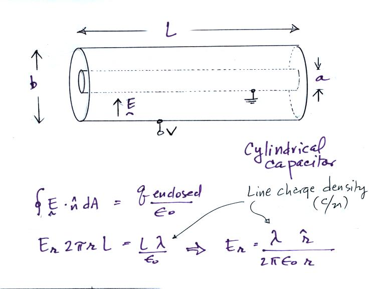
We sort of implicity assume that we
are looking a just a small section in the middle of a much longer
cylinder. The E field has just a radial component in this
case. The solution we obtain above is the same as we got for the
field around an infinitely long line of charge with uniform line charge
density.
We can write the electric field in terms of the potential difference between the two cylinders.
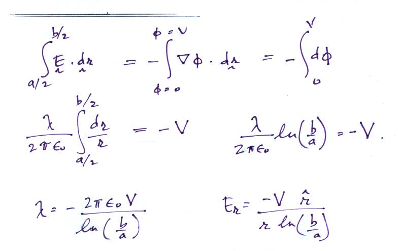
If the outer cylinder is connected to positive potential, the
grounded inner cylinder will have negative charged induced on it.
The E field will point inward as shown in the figure above. It is
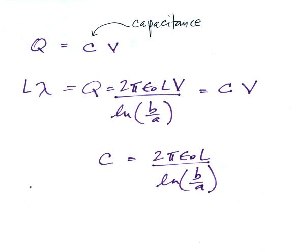
a relatively easy matter to determine the capacitance
We'll look first at how an ion counter works.
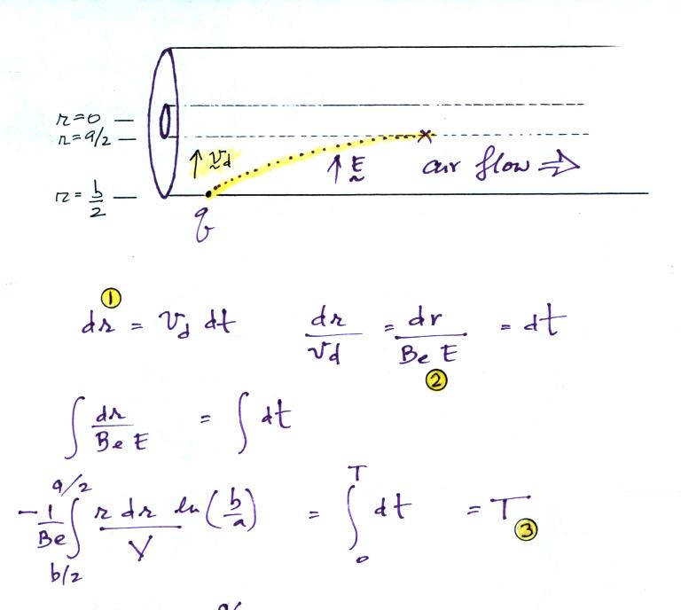
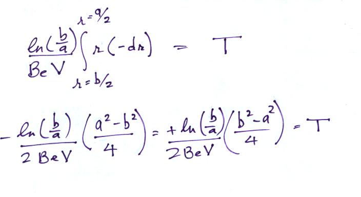
The electric field will cause a positively charged small ion entering the cylindrical capacitor at the left will drift toward the inner conductor with a drift velocity (vd). In time dt, the small ion will drift dr (Point 1). The drift velocity, Point 2, is just the electrical mobility, Be, times the electric field. T at Point 3 is the time it will take the small ion to drift from the outer cylinder to the inner cylinder.
We can write the electric field in terms of the potential difference between the two cylinders.


We'll look first at how an ion counter works.

The electric field will cause a positively charged small ion entering the cylindrical capacitor at the left will drift toward the inner conductor with a drift velocity (vd). In time dt, the small ion will drift dr (Point 1). The drift velocity, Point 2, is just the electrical mobility, Be, times the electric field. T at Point 3 is the time it will take the small ion to drift from the outer cylinder to the inner cylinder.

Now in order to be "counted" the
small ion must make it to the center conductor before it travels a
distance L (refer back to the first figure in today's notes).
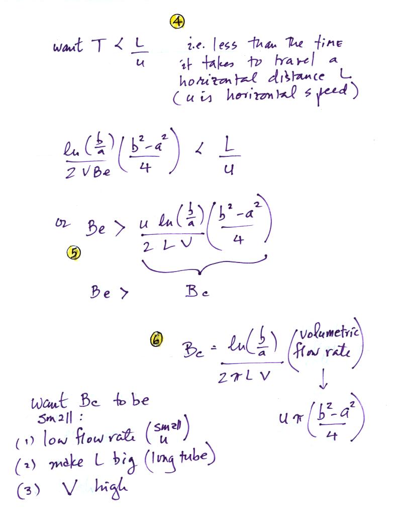
This means (Point 4) that T must be less than L/u, where u is the speed at which the air is
traveling along the length of the cylindrical capacitor (we assume u is
uniform, that there is no dependence on r).
At Point 5 we can see that, for a given value of u, Be must be greater than a certain critical mobility, Bc, in order to be collected (i.e. make it to the center conductor before traveling the length of the cylindrical capacitor).
We can write Bc in terms of a volumetric flow rate (which might actually be easier to measure than u). This is shown at Point 6.
We want Bc to be small so that all of the small ions have a mobility greater than Bc and can be counted. Clearly the lower the flow rate and the longer the tube, the more time the small ions will spend in the capacitor and the more likely they will be collected. Increasing the potential difference between the two cylinders will increase the strength of the electric field and the inward drift velocity of the small ions.
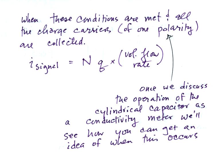

Here's the relationship between a
measured signal current (and known volumetric flow rate) and the small
ion concentration (actually, you are able to determine the
concentration times the charge per small ion).
When functioning as a conducitivty meter, only the small ions in a portion of the volume of air flowing through the cylindrical capacitor are collected (the green shaded volume in the figure below).
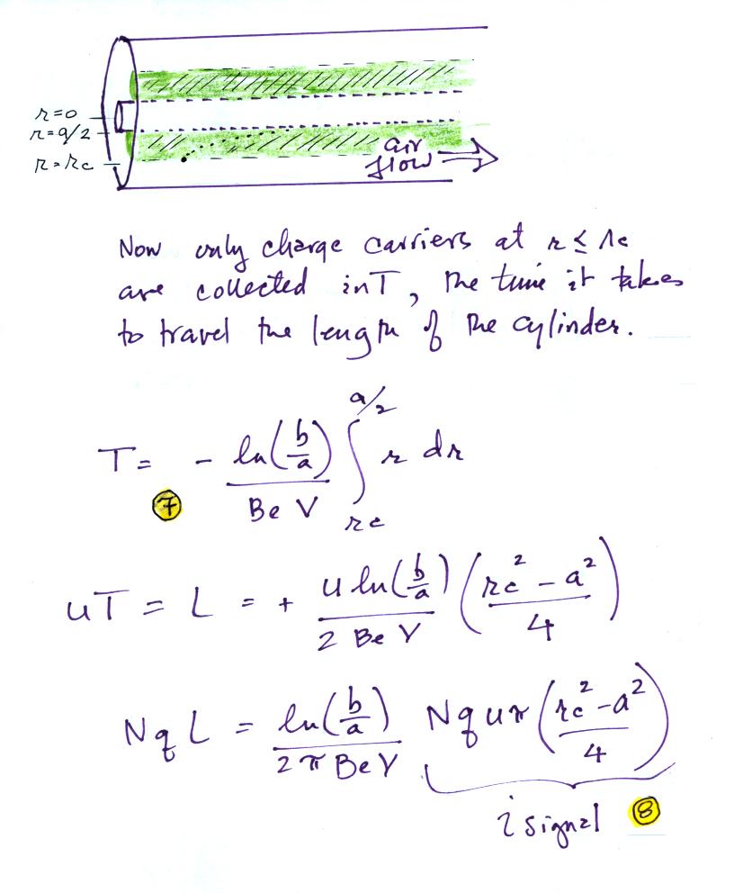
The expression at Point 7 is really just an earlier expression
(Point 3
on one of the earlier figures) with rc
replacing b/2.
At Point 8 we are multiplying the rate at which the green shaded volume is flowing through the cylinder times N q. This is the charge collected at the inner conductor per unit time and is the signal current. We need to try to relate the signal current to conductivity.
When functioning as a conducitivty meter, only the small ions in a portion of the volume of air flowing through the cylindrical capacitor are collected (the green shaded volume in the figure below).

At Point 8 we are multiplying the rate at which the green shaded volume is flowing through the cylinder times N q. This is the charge collected at the inner conductor per unit time and is the signal current. We need to try to relate the signal current to conductivity.

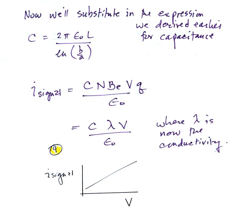
We substitute in for capacitance
and recognize that N Be q is conductivity and obtain the
expressionshown at Point 9. There is a linear relationship
between isignal and V. The slope of a plot of isignal
vs V should
provide an estimate of conductivity. And again
because we collect only one polarity of small ion we aren't measuring
the total conductivity. The total conductivity depends on charge
carriers of both polarities.
The following figure shows a conventional ion counter/conductivity meter design and an op-amp circuit that could be used to measure the signal current (Vout = signal current x R).
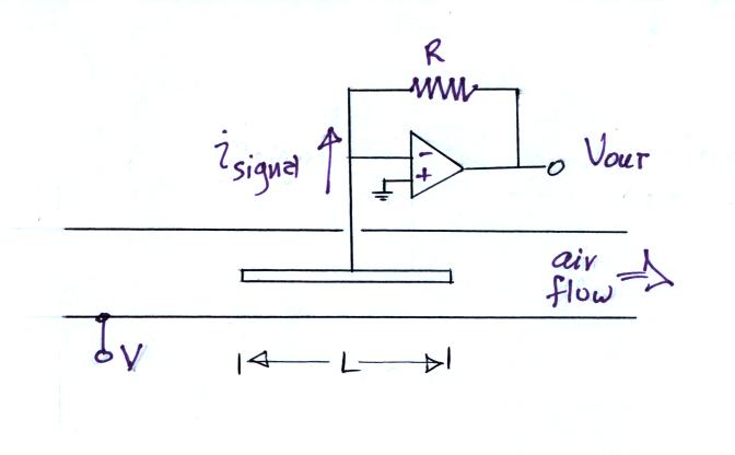
Note how the op-amp keeps the center conductor at ground potential. Because the signal current is very small, a large feedback resistor is needed in the op-amp circuit (1013 ohms was used in the "instrument" brought to class).
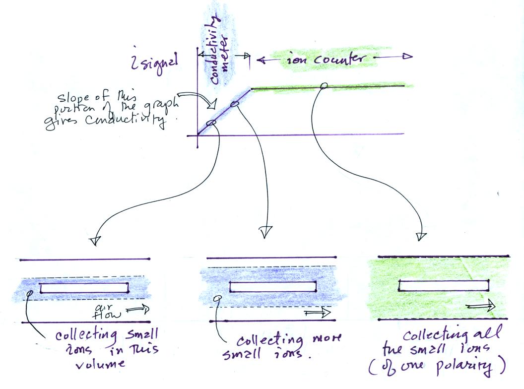
In this last figure we get a better idea of what the transition from conductivity meter to ion counter means.
For a given rate of air flow through the cylindrical capacitor we monitor the signal current as the potential difference between the outer and inner conductors is increased. As V increases small ions in a growing volume of air are collected and measured. The signal current increases. Eventually all of the small ions are collected and the signal current flattens out.
The slope of the linearly increasing, early portion of the plot provides an estimate of conductivity. The amplitude of the signal current, once it has flattened out, can be related to small ion concentration.
The following figure shows a conventional ion counter/conductivity meter design and an op-amp circuit that could be used to measure the signal current (Vout = signal current x R).

Note how the op-amp keeps the center conductor at ground potential. Because the signal current is very small, a large feedback resistor is needed in the op-amp circuit (1013 ohms was used in the "instrument" brought to class).

In this last figure we get a better idea of what the transition from conductivity meter to ion counter means.
For a given rate of air flow through the cylindrical capacitor we monitor the signal current as the potential difference between the outer and inner conductors is increased. As V increases small ions in a growing volume of air are collected and measured. The signal current increases. Eventually all of the small ions are collected and the signal current flattens out.
The slope of the linearly increasing, early portion of the plot provides an estimate of conductivity. The amplitude of the signal current, once it has flattened out, can be related to small ion concentration.