Just as in the last lecture we will consider my rental home. What sort of an over voltage might you expect on the incoming power line? Uman addresses that question in his book "The Art and Science of Lightning Protection." Apparently the insulation levels on the AC wiring in a typical home are 5,000 to 10,000 volts. This includes insulation on the wiring, in wall outlets, lamp fixtures, switches, and that sort of thing. So this is an upper limit, anything larger than this will breakdown the insulation and short to ground. In one respect the household wiring itself acts as a Surge Protection Device (SPD also formerly known as a Transient Voltage Surge Supressor). Transients on power lines are usually much lower, a few 100s of volts. In the upper 1% of cases overvoltages might range from 300 volts to a few 1000s of volts (the latter coming from a nearby strike).
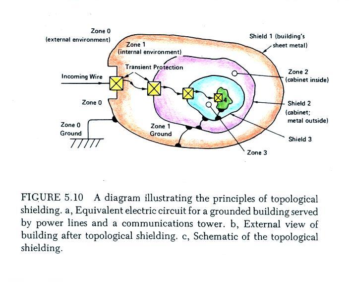
One of the first protection considerations is the concept of topological shielding. This consists of nested enclosures that might each offer some degree of shielding. Incoming transients are reduced at the entrance to each successive enclosure. The idea is shown on the figure reproduced below (source: "Applications of Advances in Lightning Research to Lightning Protection," M.A. Uman, Ch. 5 in The Earth's Electrical Environment, National Academy Press, 1986. available online)
In a home the
first line of defense could be surge protection
outside the home at the circuit breaker box where
electrical service arrives at the home. Once
in the home plugging sensitive electronic
equipment into a surge protector would offer
additional protection. The electronics
equipment itself will often have surge protection
installed.
What might the transient protection look like. In the most general terms it will probably consist of a blocking impedance followed by a shunt impedance.
What might the transient protection look like. In the most general terms it will probably consist of a blocking impedance followed by a shunt impedance.
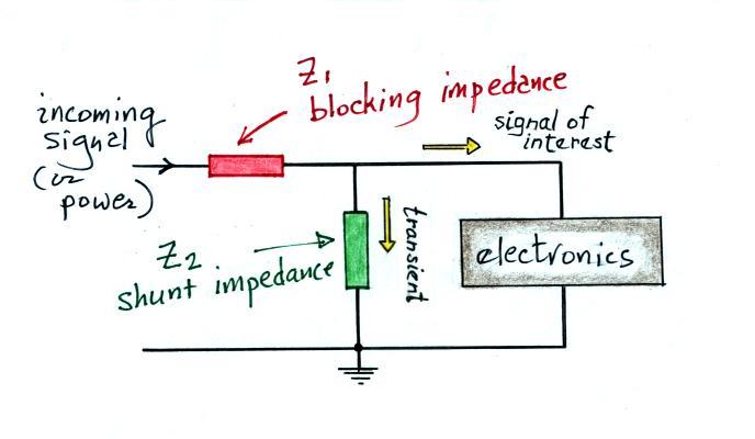
The blocking
impedance should present a high impedance to the
transient signal to prevent it from reaching the
electronics. The shunt has a low impedance
and will divert the transient signal to ground.
For the signal of interest, Z1 should appear as a low impedance. You might use an inductor if the incoming signal is low frequency (60 Hz power for example) and you want to block high frequency transients. If the incoming signal is high frequency, a capacitor would block low frequency transients.
The shunt resistance should appear as a high impedance for the signal of interest, a capacitor if the incoming signal is low frequency.
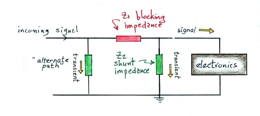
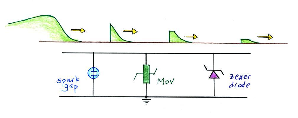
I have heard it is a good idea to provide an alternate path to an incoming signal that encounters a blocking impedance (though the blocking impedance may also cause the transient signal to be reflected rather than diverted). I.e. something like the following:
For the signal of interest, Z1 should appear as a low impedance. You might use an inductor if the incoming signal is low frequency (60 Hz power for example) and you want to block high frequency transients. If the incoming signal is high frequency, a capacitor would block low frequency transients.
The shunt resistance should appear as a high impedance for the signal of interest, a capacitor if the incoming signal is low frequency.
I have heard it is a good idea to provide an alternate path to an incoming signal that encounters a blocking impedance (though the blocking impedance may also cause the transient signal to be reflected rather than diverted). I.e. something like the following:
The first component is often a gas discharge tube.
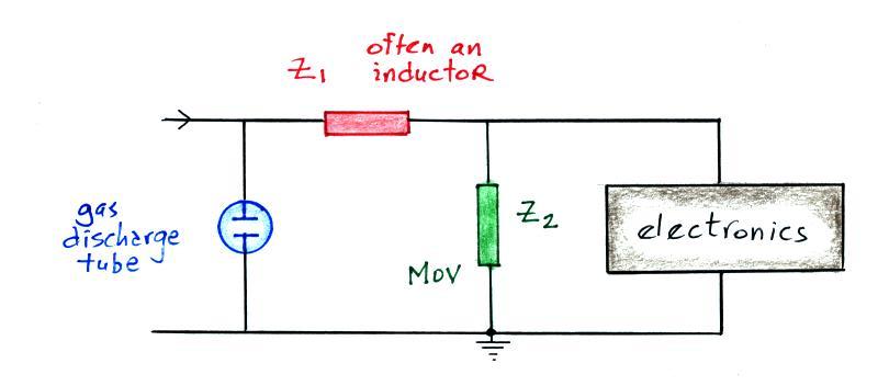
A gas discharge
tube or "spark gap" is an example of a "crowbar"
device. It creates a short circuit (like
putting
a crowbar across the signal leads) once
it exceeds a certain voltage threshold. The
figure below (from Uman's lightning protection
book) shows the operating characteristics of a
typical gas discharge tube.
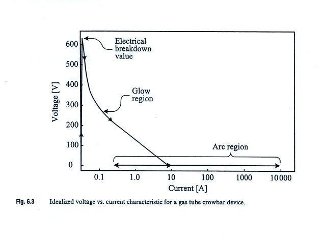
The spark gap
depicted here quickly becomes conducting once a
voltage threshold of about 600 volts is
crossed. Spark gaps can carry large
currents and are bipolar. They turn on
relatively slowly however (~1 μs). Note
that once created the arc discharge can be
maintained even at low current levels. A
device like this is sometimes difficult to "turn
off."
The role of the gas discharge tube is not to carry or divert all of the transient signal to ground. Rather the transient signal is reflected back in the direction it came from. A short discussion of reflection at the end of a short-circuited line and a line with infinite impedance (open circuit) has been added to the end of today's notes.
MOV in the figure stands for metal oxide varistor. A varistor is a voltage-controlled resistor. The operating characteristics are shown below (again from Uman's book). Varistors are clamping devices which means they hold or limit the voltage to a particular value.
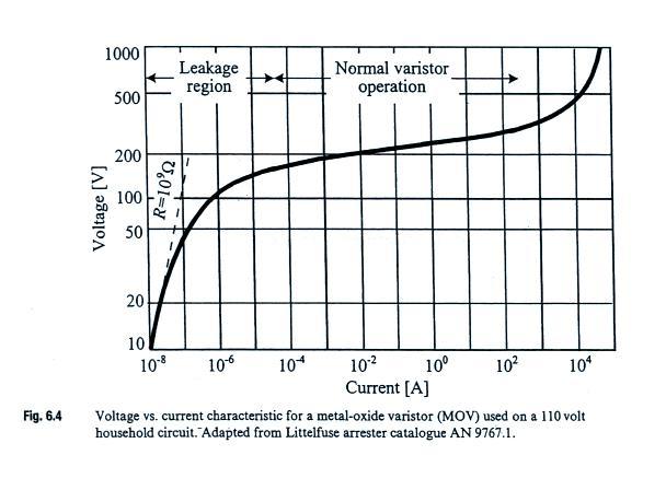
In the figure above, the varistor becomes active when the voltage across it reaches perhaps 180 volts (prior to that it has a large impedance). The voltage is then held at about that value until the current through the varistor reaches perhaps 100 A (currents higher than that would presumably destroy the device). A 200 v clamping voltage would be appropriate for a 110 volt AC power line. MOVs turn on very quickly (nanoseconds) and are bipolar. They do however have a relatively high capacitance and are not able to divert overvoltages for a sustained period of time.
The MOV could be followed by another shunt impedance such as a zener diode which would clamp the incoming signal to an even lower voltage. This is sketched below. Each device adds some additional attenuation of the transient signal.
The role of the gas discharge tube is not to carry or divert all of the transient signal to ground. Rather the transient signal is reflected back in the direction it came from. A short discussion of reflection at the end of a short-circuited line and a line with infinite impedance (open circuit) has been added to the end of today's notes.
MOV in the figure stands for metal oxide varistor. A varistor is a voltage-controlled resistor. The operating characteristics are shown below (again from Uman's book). Varistors are clamping devices which means they hold or limit the voltage to a particular value.
In the figure above, the varistor becomes active when the voltage across it reaches perhaps 180 volts (prior to that it has a large impedance). The voltage is then held at about that value until the current through the varistor reaches perhaps 100 A (currents higher than that would presumably destroy the device). A 200 v clamping voltage would be appropriate for a 110 volt AC power line. MOVs turn on very quickly (nanoseconds) and are bipolar. They do however have a relatively high capacitance and are not able to divert overvoltages for a sustained period of time.
The MOV could be followed by another shunt impedance such as a zener diode which would clamp the incoming signal to an even lower voltage. This is sketched below. Each device adds some additional attenuation of the transient signal.
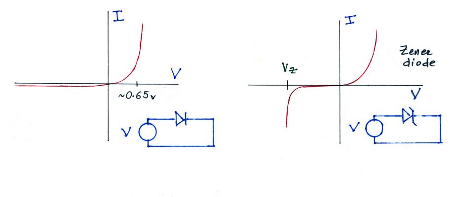
The figure below
contrasts the operation of an ordinary
diode and a zener diode.
Lightning deaths and injuries are probably underreported. There are about 100 people killed in the US every year by lightning and 1000 people are injured. This is more than for any other storm related phenomena except for floods.
The primary causes of death from lightning are cardiopulmonary arrest and damage to the central nervous system. I had always thought that someone struck by lightning would be seriously burned (internally and externally). This is apparently not the case, the duration of the lightning current is too short. Sometimes a person's clothing catches on fire, however, and that can cause serious burns.
A lightning strike can cause eye damage and hearing loss (one or both eardrums is(are) often ruptured). Psychological effects (anxiety, fatigue, chronic headaches or other pain, personality changes and depression) are apparently a significant and long lasting result of a lightning strike.
Telephone injury is the most common type of indoors injury associated with lightning.
I would encourage you to read "Updated Recommendations for Lightning Safety - 1998" by R.L. Holle, R.E. Lopez and C. Zimmerman if you ever find yourself in a situation where you might be responsible for providing lightning safety recommendations or warning to a group of people.
You should also be aware of the National Lightning Safety Institute , an organization that is dedicated to providing accurate lightning safety information and interested in lightning safety education.
Lastly I'll mention the The 30/30 Rule. Basically if there is less than 30 seconds between a lightning flash and the sound of the thunder, that lightning discharge is close enough to present a risk to you. You should be under cover. You should wait 30 minutes after the last lightning discharge from a thunderstorm before concluding that the storm no longer presents a lightning hazard to you.
The left figure
shows a conventional diode.
The diode begins to conduct when the
forward bias voltage reaches about
0.65 volts. Very little
current flows through the diode when
back biased. The zener diode
at right operates in the same way
when forward biased.
When back biased the diode doesn't
conduct much current until the
voltage reaches a breakdown or zener
voltage (Vz). Then
voltage will be maintained at Vz
over a wide range of currents.
In addition to use as a surge
protective device, zener diodes are
also used as voltage
regulators. Note that a zener
diode is not a bipolar device, it
offers surge protection against only
one polarity of overvoltage.
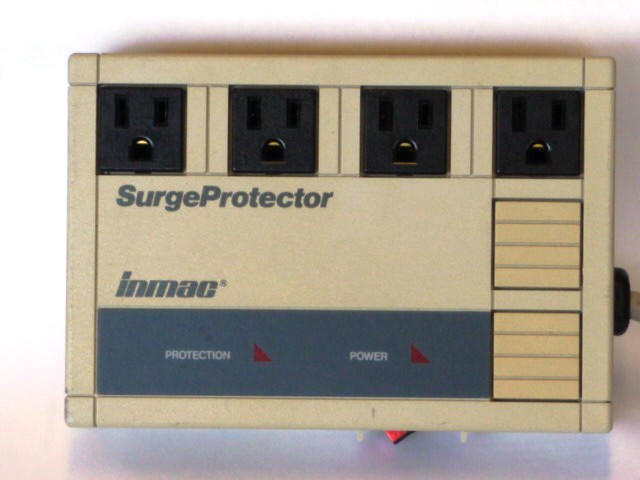
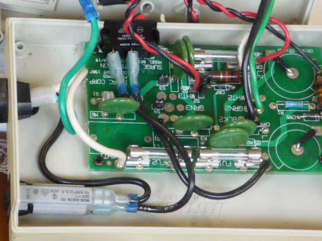
Many of the devices we have been discussing can be found inside a commercial surge protector (in this case an Inmac 8215 Surge Protector)
Finally a few notes from the
chapter on medical issues and personal
lightning safety in Uman's lightning
protection book.Many of the devices we have been discussing can be found inside a commercial surge protector (in this case an Inmac 8215 Surge Protector)
A gas
discharge tube can be seen near
the center left edge of the
printed circuit board (white
ceramic case). A total of
6 MOVs can be seen. They
are green, circular, and might
otherwise be mistaken for
capacitors. There is room
for two inductors on the circuit
board (the two circles printed
on the right side of the circuit
board). The inductors are
apparently not included in this
model.
Lightning deaths and injuries are probably underreported. There are about 100 people killed in the US every year by lightning and 1000 people are injured. This is more than for any other storm related phenomena except for floods.
The primary causes of death from lightning are cardiopulmonary arrest and damage to the central nervous system. I had always thought that someone struck by lightning would be seriously burned (internally and externally). This is apparently not the case, the duration of the lightning current is too short. Sometimes a person's clothing catches on fire, however, and that can cause serious burns.
A lightning strike can cause eye damage and hearing loss (one or both eardrums is(are) often ruptured). Psychological effects (anxiety, fatigue, chronic headaches or other pain, personality changes and depression) are apparently a significant and long lasting result of a lightning strike.
Telephone injury is the most common type of indoors injury associated with lightning.
I would encourage you to read "Updated Recommendations for Lightning Safety - 1998" by R.L. Holle, R.E. Lopez and C. Zimmerman if you ever find yourself in a situation where you might be responsible for providing lightning safety recommendations or warning to a group of people.
You should also be aware of the National Lightning Safety Institute , an organization that is dedicated to providing accurate lightning safety information and interested in lightning safety education.
Lastly I'll mention the The 30/30 Rule. Basically if there is less than 30 seconds between a lightning flash and the sound of the thunder, that lightning discharge is close enough to present a risk to you. You should be under cover. You should wait 30 minutes after the last lightning discharge from a thunderstorm before concluding that the storm no longer presents a lightning hazard to you.
We had time at the end of the class period to begin a short section on lightning spectroscopy. That has been moved over to the Apr. 11 notes so that it will all be together in one place.
Here's a short look at what happens to a voltage pulse when it arrives at the end of a transmission line. We look first at the case of an open circuit (infinite terminating impedance) at the end of the line.
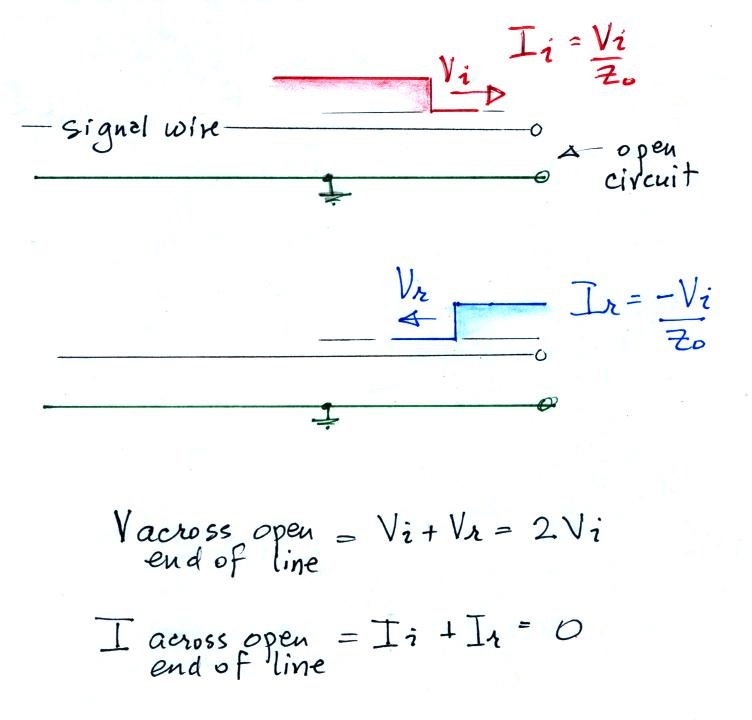
The top of the figure shows an incoming voltage pulse with amplitude Vi arriving at the end of the line. The current associated with this pulse is Vi/Zo where Zo is the characteristic impedance of the line.
Because of the infinite terminating impedance, there can be no current flow across the end of the line. A reflected voltage pulse, Vr, with the same polarity and amplitude as in the incoming pulse is produced. The reflected current is -Vi/Zo.
Thus at the open end of the line you would measure a voltage V equal to twice the amplitude of the incoming pulse (the superposition of the incoming and reflected pulses) and zero current.
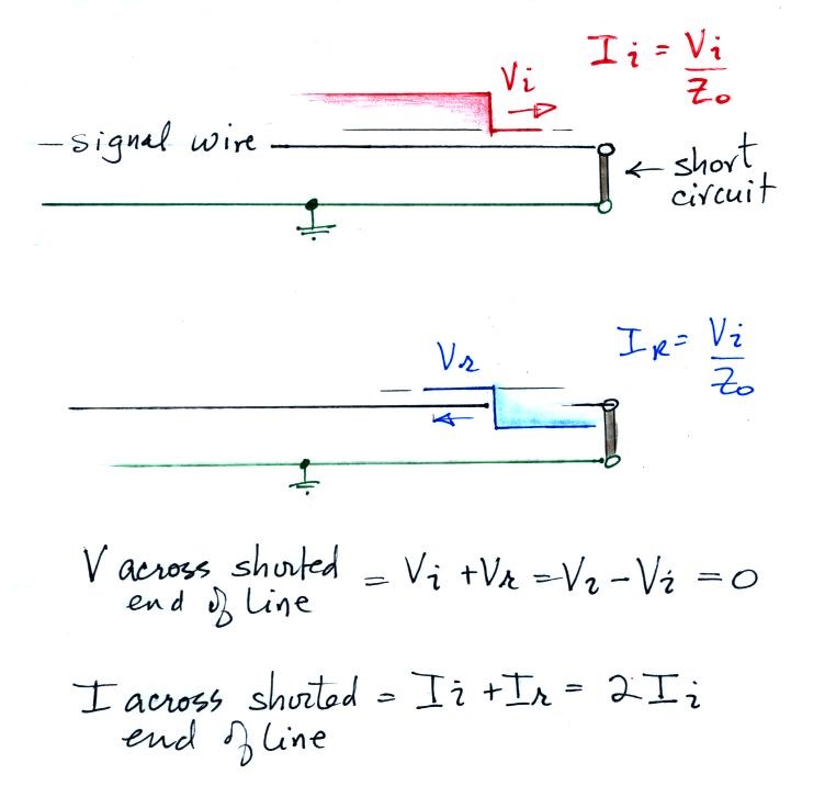
This figure shows the same
voltage pulse, Vi, arriving at the end of a
shorted line. Now the requirement is
that the voltage at the end of the line be
zero. The reflected voltage pulse has
opposite polarity but the same amplitude as
the incoming pulse. The reflected
current is equal to the incoming current.
The measured voltage at the end of the line is zero. The current at the end of the line has an amplitude that is twice the incoming current.
The measured voltage at the end of the line is zero. The current at the end of the line has an amplitude that is twice the incoming current.